REAR DIFFERENTIAL CARRIER ASSEMBLY(for LSD) DISASSEMBLY

PROCEDURE
-
INSPECT RUNOUT OF REAR DRIVE PINION COMPANION FLANGE
-
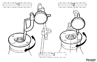
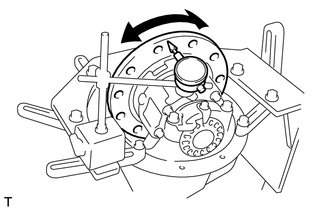
*1 Vertical Runout: *2 Lateral Runout: *3 35 mm (1.38 in.) Using a dial indicator, measure the runout of the companion flange vertically and laterally.
Maximum Runout Runout Specified Condition Vertical runout 0.10 mm (0.00394 in.) Lateral runout 0.10 mm (0.00394 in.) If the runout is more than the maximum, replace the companion flange.
-
-
INSPECT RUNOUT OF DIFFERENTIAL RING GEAR
-
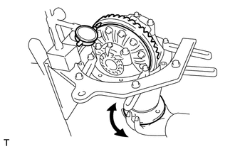
Using a dial indicator, measure the ring gear runout.
Maximum runout 0.05 mm (0.00197 in.) If the runout is more than the maximum, replace the ring gear.
-
-
INSPECT DIFFERENTIAL RING GEAR BACKLASH
-
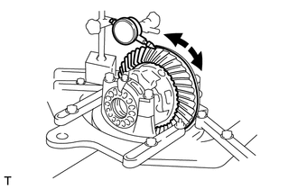
Using a dial indicator, measure the ring gear backlash.
Standard backlash 0.10 to 0.20 mm (0.00394 to 0.00787 in.) Tech Tips
Measure at 3 or more positions around the circumference of the ring gear.
If the backlash is not as specified, adjust the side bearing preload or repair as necessary.
-
-
REMOVE DRIVE PINION COMPANION FLANGE REAR NUT
-
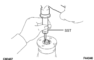
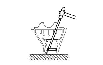
Using SST and a hammer, unstake the nut.
- SST
- 09930-00010
-
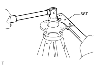
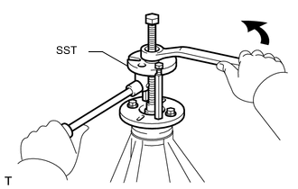
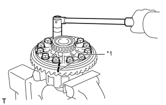
Using SST to hold the flange, remove the nut.
- SST
- 09330-00021 ( 09330-00030 )
-
-
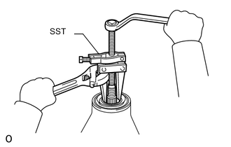
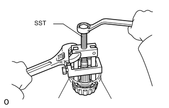
REMOVE REAR DRIVE PINION COMPANION FLANGE REAR SUB-ASSEMBLY
-
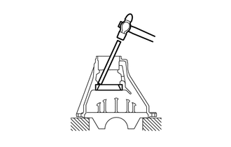
Using SST, remove the companion flange.
- SST
- 09950-30012 ( 09951-03010, 09953-03010, 09954-03010, 09955-03030, 09956-03040 )
-
-
REMOVE REAR DIFFERENTIAL CARRIER OIL SEAL
-
Using SST, remove the oil seal from the differential carrier.
- SST
- 09308-10010
-
-
REMOVE REAR DIFFERENTIAL DRIVE PINION OIL SLINGER
-
REMOVE REAR DRIVE PINION FRONT TAPERED ROLLER BEARING
-
Using SST, remove the front bearing (inner race) from the drive pinion.
- SST
- 09556-22010
If the front bearing is damaged or worn, replace the bearing.
-
-
REMOVE REAR DIFFERENTIAL BEARING ADJUSTING NUT LOCK
-
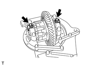
Remove the 2 bolts and 2 adjusting nut locks.
-
-
REMOVE DIFFERENTIAL CASE ASSEMBLY
-
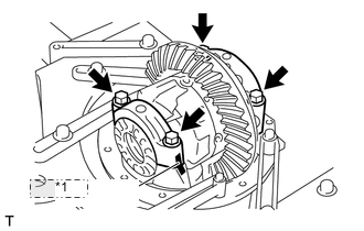
*1 Matchmark Place matchmarks on the bearing caps and differential carrier.
-
Remove the 4 bolts, 2 bearing caps, 2 adjusting nuts and 2 bearings (outer race).
-
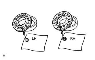
Remove the differential case from the differential carrier.
Tech Tips
Tag the 2 case bearing outer races to show the location for reassembly.
-
-
REMOVE DIFFERENTIAL DRIVE PINION
-
Remove the differential drive pinion from the differential carrier.
-
-
REMOVE REAR DIFFERENTIAL DRIVE PINION BEARING SPACER
-
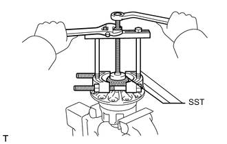
REMOVE REAR DRIVE PINION REAR TAPERED ROLLER BEARING
-
Using SST and a press, press out the bearing (inner race).
- SST
- 09950-00020
If either the drive pinion or ring gear is damaged, replace them as a set.
-
-
REMOVE REAR DIFFERENTIAL DRIVE PINION PLATE WASHER
-
REMOVE REAR DRIVE PINION FRONT TAPERED ROLLER BEARING
-
Using a brass bar and hammer, tap out the bearing (outer race).
-
-
REMOVE REAR DRIVE PINION REAR TAPERED ROLLER BEARING
-
Using a brass bar and hammer, tap out the bearing (outer race).
-
-
REMOVE DIFFERENTIAL RING GEAR
-
*1 Matchmark Place matchmarks on the ring gear and differential case.
-
Remove the 12 ring gear set bolts.
-
Using a plastic-faced hammer, tap on the ring gear to separate it from the differential case.
-
-
INSPECT RUNOUT OF DIFFERENTIAL CASE
Tech Tips
If the ring gear runout is at the maximum or less (refer to the "Inspect Runout of Differential Ring Gear" procedure), this inspection is not necessary.
-
Install the differential case to the differential carrier.
-
Using a dial indicator, measure the differential case runout.
Maximum runout 0.04 mm (0.00157 in.) If the runout is more than the maximum, replace the differential case and side bearings as a set.
-
Remove the differential case from the differential carrier.
-
-
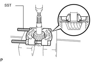
REMOVE REAR DIFFERENTIAL CASE BEARING
-
Using SST, remove the 2 side bearings (inner race) from the differential case.
- SST
- 09950-00020
- 09950-00030
- 09950-40011 ( 09957-04010 )
- 09950-60010 ( 09951-00480 )
-
-
DISASSEMBLE DIFFERENTIAL CASE
-
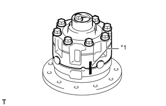
*1 Matchmark Place matchmarks on the differential case LH and RH.
-
Remove the 8 bolts uniformly, a little at a time.
-
Using a plastic-faced hammer, separate the differential case LH and RH.
-
Remove the 2 side gears, 6 side gear thrust washers, 4 clutch plates, 2 spring retainers, compression spring, 4 pinion gears, 4 pinion gear thrust washers and spider from the differential case.
Tech Tips
-
Keep the disassembled parts in order.
-
If the side gear backlash has been adjusted by a TOYOTA dealer, adjusting shims are installed between the side gear thrust washer and the differential case.
If replacing a side gear, also replace the thrust washer that contacts it.
-
-
-
INSPECT REAR DIFFERENTIAL SIDE GEAR THRUST WASHER
Tech Tips
If replacing the thrust washer, also replace the clutch plate that contacts it.
-
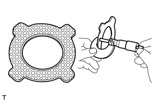
Using a micrometer, check that the thickness of the thrust washer is even.
Thickness (Reference) 1.97 to 2.06 mm (0.0776 to 0.0811 in.) If necessary, replace the thrust washer.
-
Visually check the thrust washer.
If bare metal is showing, replace the thrust washer.
-
-
INSPECT CLUTCH PLATE
-
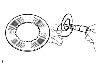
Using a micrometer, check that the thickness of the clutch plate is even.
Thickness (Reference) 1.97 to 2.03 mm (0.0776 to 0.0799 in.) If necessary, replace the clutch plate.
-
-
INSPECT COMPRESSION SPRING
-
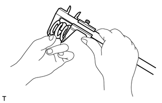
Using vernier caliper, measure the free length of the spring.
Length (Reference) 32.8 mm (1.29134 in.) If necessary, replace the compression spring.
-