PROCEDURE
- Click here
INSTALL FRONT PROPELLER SHAFT UNIVERSAL JOINT SPIDER ASSEMBLY
-
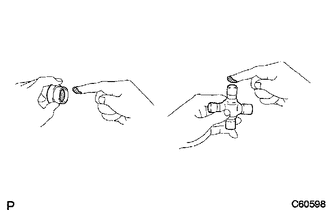
Apply MP grease to a new spider and new bearings.
Note:Be careful not to apply too much grease.
-
Fit the spider into the flange yoke.
-
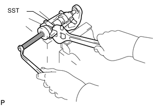
Using SST, install the bearings to the spider.
09332-25010 -
Using SST, adjust both bearings so that the snap ring grooves are at maximum and equal in width.
09332-25010 -
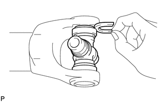
Install 2 new snap rings of equal thickness which will allow 0 mm (0 in.) of axial play.
Tip:Do not reuse the snap rings.
Standard Snap Ring Thickness Color Mark Specified Condition - J 2.18 to 2.20 mm (0.0858 to 0.0866 in.) - K 2.20 to 2.22 mm (0.0866 to 0.0874 in.) - F 2.22 to 2.24 mm (0.0874 to 0.0882 in.) - G 2.24 to 2.26 mm (0.0882 to 0.0890 in.) - H 2.26 to 2.28 mm (0.0890 to 0.0898 in.) - 1 2.28 to 2.30 mm (0.0898 to 0.0906 in.) - 2 2.30 to 2.32 mm (0.0906 to 0.0913 in.) - - 2.32 to 2.34 mm (0.0913 to 0.0921 in.) Brown - 2.34 to 2.36 mm (0.0921 to 0.0929 in.) Blue - 2.36 to 2.38 mm (0.0929 to 0.0937 in.) - 6 2.38 to 2.40 mm (0.0937 to 0.0945 in.) - 7 2.40 to 2.42 mm (0.0945 to 0.0953 in.) - 8 2.42 to 2.44 mm (0.0953 to 0.0961 in.) - 
2.44 to 2.46 mm (0.0961 to 0.0969 in.) - 10 2.46 to 2.48 mm (0.0969 to 0.0976 in.) - A 2.48 to 2.50 mm (0.0976 to 0.0984 in.) - B 2.50 to 2.52 mm (0.0984 to 0.0992 in.) - C 2.52 to 2.54 mm (0.0992 to 0.1000 in.) - D 2.54 to 2.56 mm (0.1000 to 0.1008 in.) - E 2.56 to 2.58 mm (0.1008 to 0.1016 in.) -
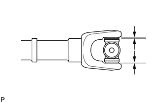
Using a hammer, tap the yoke until there is no clearance between the bearing outer race and snap ring.
-
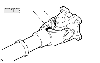
Table 1. *1 Matchmark Align the matchmarks on the propeller shaft and flange yoke or flange yoke and sleeve yoke.
-
Install the flange yoke to the sleeve yoke or propeller shaft.
Tip:Install 2 new spider bearings and snap rings on the flange yoke side using the procedure described above.
-
- Click here
APPLY MP GREASE
-
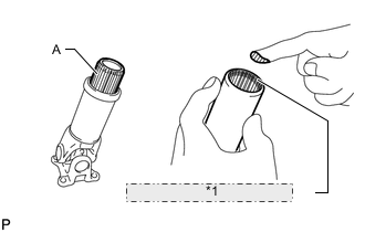
Table 2. *1 MP Grease Application Area Apply MP grease to the propeller shaft (the edge of the spline) as shown in the illustration.
Amount (Reference) Spline A Amount Silver 44 to 54 g (1.56 to 1.90 oz.) Black 9 to 17 g (0.32 to 0.59 oz.) Tip:The amount of grease differs depending on the color of the spline portion of the sleeve yoke.
-
Align the matchmarks and install the sleeve yoke to the propeller shaft.
Note:
-
Do not scratch the spline portion.
-
Make sure that there is no foreign matter.
-
-
-
Click here
INSPECT PROPELLER SHAFT GREASE FITTING DIRECTION
Tip:When replacing a spider bearing, be sure that the grease fitting hole is facing the direction shown in the illustration.
- Click here
INSPECT SPIDER BEARING