4WD CONTROL ECU(for RHD) REMOVAL
PROCEDURE
-
PRECAUTION
Note
After turning the ignition switch off, waiting time may be required before disconnecting the cable from the negative (-) battery terminal. Therefore, make sure to read the disconnecting the cable from the negative (-) battery terminal notice before proceeding with work Click here.
-
DISCONNECT CABLE FROM NEGATIVE BATTERY TERMINAL
CAUTION:
w/ Driver Side Knee Airbag:
Wait at least 90 seconds after disconnecting the cable from the negative (-) battery terminal to disable the SRS system.
Note
When disconnecting the cable, some systems need to be initialized after the cable is reconnected Click here.
-
REMOVE NO. 1 INSTRUMENT PANEL FINISH PANEL CUSHION
-
REMOVE LOWER INSTRUMENT PANEL PAD SUB-ASSEMBLY RH
-
REMOVE NO. 1 INSTRUMENT CLUSTER FINISH PANEL GARNISH
-
REMOVE NO. 2 INSTRUMENT CLUSTER FINISH PANEL GARNISH
-
REMOVE FRONT DOOR SCUFF PLATE RH
-
REMOVE NO. 1 INSTRUMENT PANEL UNDER COVER SUB-ASSEMBLY (w/ Floor Under Cover)
-
REMOVE COWL SIDE TRIM BOARD RH
-
REMOVE LOWER NO. 1 INSTRUMENT PANEL FINISH PANEL
-
REMOVE NO. 1 SWITCH HOLE BASE
-
REMOVE DRIVER SIDE KNEE AIRBAG ASSEMBLY (w/ Driver Side Knee Airbag)
-
REMOVE LOWER INSTRUMENT PANEL SUB-ASSEMBLY (w/o Driver Side Knee Airbag)
-
REMOVE STEERING CONTROL WITH JUNCTION BLOCK
-
REMOVE 4 WHEEL DRIVE CONTROL ECU
-
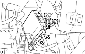
Remove the bolt.
-
Detach the 2 guides and disconnect the 4 wheel drive control ECU.
-
Disconnect the 2 connectors from the 4 wheel drive control ECU.
-