TRANSFER ASSEMBLY INSPECTION

PROCEDURE
-
INSPECT TRANSFER INPUT SHAFT
-

Using a micrometer, measure the diameter of the input shaft journal surface.
Minimum diameter 68 mm (2.68 in.) If the diameter is less than the minimum, replace the input shaft.
-
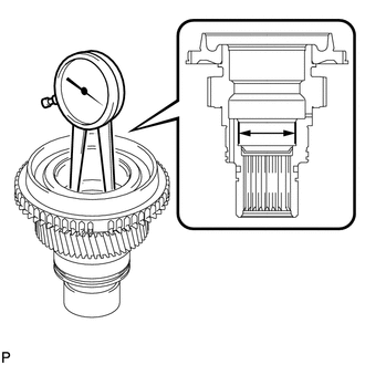
Using a dial indicator, measure the inside diameter of the input shaft bush.
Maximum inside diameter 46 mm (1.81 in.) If the inside diameter is more than the maximum, replace the input shaft.
-
-
INSPECT TRANSFER LOW PLANETARY GEAR ASSEMBLY
-
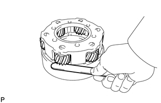
Using a feeler gauge, measure the thrust clearance of the pinion gear.
Standard clearance 0.11 to 0.85 mm (0.00434 to 0.0334 in.) Maximum clearance 0.85 mm (0.0334 in.) If the clearance is more than the maximum, replace the low planetary gear assembly.
-
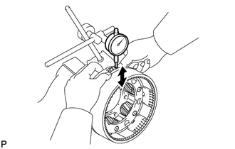
Using a dial indicator, measure the radial clearance of the pinion gear.
Standard clearance 0.01 to 0.04 mm (0.000394 to 0.00157 in.) Maximum clearance 0.04 mm (0.00157 in.) If the clearance is more than the maximum, replace the low planetary gear assembly.
-
-
INSPECT REAR TRANSFER OUTPUT SHAFT
-
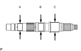
Using a micrometer, measure the diameter of the output shaft journals.
Minimum Diameter Journal Specified Condition A 38 mm (1.50 in.) B 42 mm (1.65 in.) C 49 mm (1.93 in.) If the diameter is less than the minimum, replace the output shaft.
-
-
INSPECT NO. 1 TRANSFER GEAR SHIFT FORK AND FRONT DRIVE CLUTCH SLEEVE
-
Using a feeler gauge, measure the clearance between the clutch sleeve and gear shift fork.
Maximum clearance 0.8 mm (0.0315 in.) If the clearance is more than the maximum, replace the clutch sleeve or shift fork.
-
-
INSPECT NO. 2 TRANSFER GEAR SHIFT FORK AND HIGH AND LOW CLUTCH SLEEVE
-
Using a feeler gauge, measure the clearance between the clutch sleeve and gear shift fork.
Maximum clearance 3.15 mm (0.124 in.) If the clearance is more than the maximum, replace the clutch sleeve or shift fork.
-
-
INSPECT NO. 1 SYNCHRONIZER RING (for Manual Transmission)
-
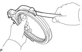
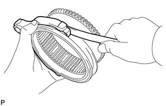
Apply gear oil to the cone of the input shaft, and check that it does not turn in both directions while pushing the No. 1 synchronizer ring.
If it can turn, replace the No. 1 synchronizer ring.
-
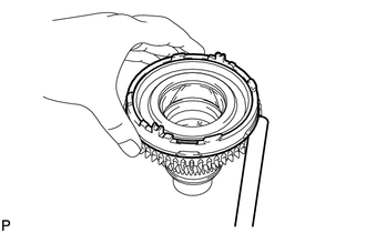
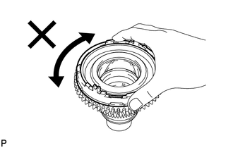
Push the No. 1 synchronizer ring to the cone of the input shaft. Measure the clearance between the No. 1 synchronizer ring and input shaft.
Standard clearance 0.86 to 1.54 mm (0.0339 to 0.0606 in.) Minimum clearance 0.86 mm (0.0339 in.) If the clearance is not as specified, replace the No. 1 synchronizer ring with a new one.
-
-
INSPECT TRANSFER SHIFT ACTUATOR ASSEMBLY (HIGH-LOW TRANSFER SHIFT ACTUATOR)
-
Check the high-low transfer shift actuator.
-
Check the high to low switch.
-
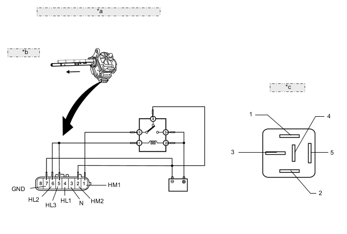
Connect lines via a relay as shown in the illustration, and check that the actuator fork moves from the high to low position.
Note
-
Make sure to perform this inspection with the actuator removed from the vehicle. If this inspection is performed with the actuator installed to the vehicle, the actuator will be damaged.
-
When inspecting the actuator, make sure to operate it with the lines connected via a relay. If the lines are not connected via a relay and battery voltage is directly applied to the actuator, the actuator will be damaged.
Tech Tips
When performing the operation described above, use the DEFOG relay.

*a Component without harness connected: (High-low Transfer Shift Actuator) *b High → Low: *c DEFOG Relay: -
-
After the high to low switch is complete, check the neutral position detection switch and limit switch.
-
Measure the resistance according to the value(s) in the table below.
Standard Resistance Tester Connection Condition Specified Condition 3 (N)* - 7 (GND) After high to low switch is complete 10 kΩ or higher 4 (HL1) - 7 (GND) After high to low switch is complete 10 kΩ or higher 5 (HL3) - 7 (GND) After high to low switch is complete 10 kΩ or higher 6 (HL2) - 7 (GND) After high to low switch is complete Below 1 Ω *: for Manual Transmission
If there is a malfunction, replace the transfer shift actuator assembly.
-
-
Check the low to high switch.
-
Connect lines via a relay as shown in the illustration, and check that the actuator fork moves from the low to high position.
Note
-
Make sure to perform this inspection with the actuator removed from the vehicle. If this inspection is performed with the actuator installed to the vehicle, the actuator will be damaged.
-
When inspecting the actuator, make sure to operate it with the lines connected via a relay. If the lines are not connected via a relay and battery voltage is directly applied to the actuator, the actuator will be damaged.
Tech Tips
When performing the operation described above, use the DEFOG relay.
*a Component without harness connected: (High-low Transfer Shift Actuator) *b High ← Low: *c DEFOG Relay: -
-
After the low to high switch is complete, check the neutral position detection switch and limit switch.
-
Measure the resistance according to the value(s) in the table below.
Standard Resistance Tester Connection Condition Specified Condition 3 (N)* - 7 (GND) After low to high switch is complete 10 kΩ or higher 4 (HL1) - 7 (GND) After low to high switch is complete Below 1 Ω 5 (HL3) - 7 (GND) After low to high switch is complete 10 kΩ or higher 6 (HL2) - 7 (GND) After low to high switch is complete 10 kΩ or higher *: for Manual Transmission
If there is a malfunction, replace the transfer shift actuator assembly.
-
-
-
-
INSPECT TRANSFER SHIFT ACTUATOR ASSEMBLY (CENTER DIFFERENTIAL LOCK ACTUATOR)
-
Check the center differential lock actuator.
-
Check the free to lock switch.
-
Connect lines via a relay as shown in the illustration, and check that the actuator fork moves from the free to lock position.
Note
-
Make sure to perform this inspection with the actuator removed from the vehicle. If this inspection is performed with the actuator installed to the vehicle, the actuator will be damaged.
-
When inspecting the actuator, make sure to operate it with the lines connected via a relay. If the lines are not connected via a relay and battery voltage is directly applied to the actuator, the actuator will be damaged.
Tech Tips
When performing the operation described above, use the DEFOG relay.
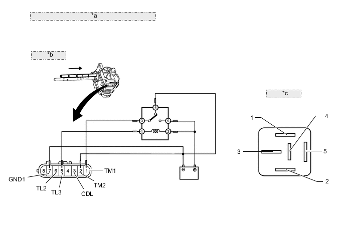
*a Component without harness connected: (Center Differential Lock Actuator) *b Free → Lock: *c DEFOG Relay: -
-
After the free to lock switch is complete, check the center differential lock detection switch and limit switch.
-
Measure the resistance according to the value(s) in the table below.
Standard Resistance Tester Connection Condition Specified Condition 3 (CDL) - 7 (GND1) After free to lock switch is complete Below 1 Ω 5 (TL3) - 7 (GND1) After free to lock switch is complete 10 kΩ or higher 6 (TL2) - 7 (GND1) After free to lock switch is complete Below 1 Ω If there is a malfunction, replace the transfer shift actuator assembly.
-
-
Check the lock to free switch.
-
Connect lines via a relay as shown in the illustration, and check that the actuator fork moves from the lock to free position.
Note
-
Make sure to perform this inspection with the actuator removed from the vehicle. If this inspection is performed with the actuator installed to the vehicle, the actuator will be damaged.
-
When inspecting the actuator, make sure to operate it with the lines connected via a relay. If the lines are not connected via a relay and battery voltage is directly applied to the actuator, the actuator will be damaged.
Tech Tips
When performing the operation described above, use the DEFOG relay.
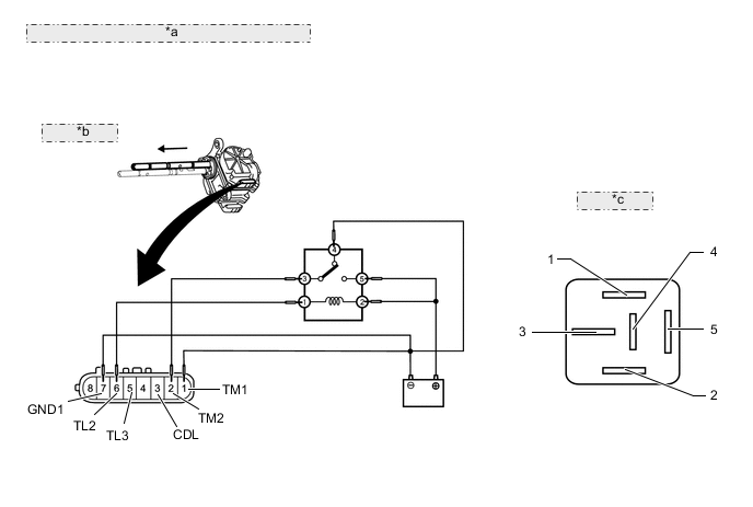
*a Component without harness connected: (Center Differential Lock Actuator) *b Free ← Lock: *c DEFOG Relay: -
-
After the lock to free switch is complete, check the center differential lock detection switch and limit switch.
-
Measure the resistance according to the value(s) in the table below.
Standard Resistance Tester Connection Condition Specified Condition 3 (CDL) - 7 (GND1) After lock to free switch is complete 10 kΩ or higher 5 (TL3) - 7 (GND1) After lock to free switch is complete Below 1 Ω 6 (TL2) - 7 (GND1) After lock to free switch is complete 10 kΩ or higher If there is a malfunction, replace the transfer shift actuator assembly.
-
-
-
-
INSPECT TRANSFER SHIFT ACTUATOR ASSEMBLY (TEMPERATURE SENSOR) (w/ Temperature Sensor)
-
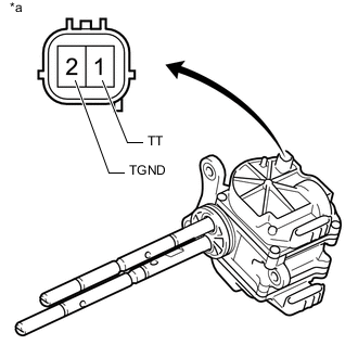
Text in Illustration *a Component without harness connected
(Temperature Sensor)
Measure the resistance according to the value(s) in the table below.
Standard Resistance Tester Connection Condition Specified Condition 1 (TT) - Body ground Always 10 kΩ or higher 2 (TGND) - Body ground Always 10 kΩ or higher -
While warming the transfer shift actuator assembly, measure the resistance according to the value(s) in the table below.
Standard Resistance Tester Connection Temperature Specified Condition 1 (TT) - 2 (TGND) 10°C (50°F) 3.61 kΩ 20°C (68°F) 2.38 kΩ 30°C (86°F) 1.61 kΩ If the result is not as specified, replace the transfer shift actuator assembly.
-