TRANSFER SYSTEM Rear Differential Lock Switch Circuit
WIRING DIAGRAM
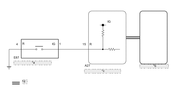
| *a | Differential Lock Switch |
| *b | Combination Meter Assembly |
| *c | 4 Wheel Drive Control ECU |
| *d | CAN Communication Line |
PROCEDURE
-
CHECK REAR DIFFERENTIAL LOCK INDICATOR LIGHT
-
Turn the ignition switch to ON.
-
Press the differential lock switch.
-
Check the rear differential lock indicator light.
Result Result Proceed to Rear differential lock indicator light blinks or illuminates A Rear differential lock indicator light remains off regardless of switch operation B Rear differential lock indicator light remains illuminated regardless of switch operation C
-
Blinking: Blinks at 0.5 second intervals (0.5 seconds on and 0.5 seconds off)
-
A 
END
C 
CHECK CAN COMMUNICATION LINE Click here
B 
-
-
CHECK CAN COMMUNICATION LINE
-
Select "Bus Check" from the System Selection Menu screen, and follow the prompts on the screen to inspect the CAN bus (for LHD with Central Gateway ECU: See page , for LHD without Central Gateway ECU: See page , for RHD with Central Gateway ECU: See page , for RHD without Central Gateway ECU: Click here.
OK "Bus Check" indicates no malfunctions in CAN communication. Result Result Proceed to DTC is not output A DTC is output for LHD with Central Gateway ECU B for LHD without Central Gateway ECU C for RHD with Central Gateway ECU D for RHD without Central Gateway ECU E
B
CHECK CAN COMMUNICATION SYSTEM Click here
C
CHECK CAN COMMUNICATION SYSTEM Click here
D
CHECK CAN COMMUNICATION SYSTEM Click here
E
CHECK CAN COMMUNICATION SYSTEM Click here
A
-
-
READ VALUE USING GTS (DIFFERENTIAL LOCK SWITCH)
-
Turn the ignition switch off.
-
Connect the GTS to the DLC3.
-
Turn the GTS on.
-
Turn the ignition switch to ON.
-
Enter the following menus: Powertrain / Four Wheel Drive / Data List.
-
According to the display on the GTS, read the Data List
Four Wheel Drive Tester Display Measurement Item/Range Normal Condition Diagnostic Note Rear Differential Lock Control SW Differential lock switch status/
ON or OFF
ON: RR (LOCK)
OFF: OFF (FREE)
Used only for vehicles with a rear differential lock.
Always displays OFF for vehicles without a rear differential lock.
OK OK: Display changes according to differential lock switch operation
NG
INSPECT DIFFERENTIAL LOCK SWITCH Click here
OK
-
-
INSPECT COMBINATION METER ASSEMBLY
-
Turn the ignition switch off.
-
Perform an Active Test of the combination meter assembly using the GTS Click here.
-
Check the combination meter assembly.
OK The rear differential lock indicator light turns on or off in accordance with the GTS. Result Result Proceed to OK for LHD A for RHD B NG C
A
REPLACE 4 WHEEL DRIVE CONTROL ECU Click here
B
REPLACE 4 WHEEL DRIVE CONTROL ECU Click here
C
CHECK METER / GAUGE SYSTEM Click here
-
-
INSPECT DIFFERENTIAL LOCK SWITCH
-
Remove the differential lock switch Click here.
-
Inspect the differential lock switch Click here.
OK The differential lock switch operates normally.
NG
REPLACE DIFFERENTIAL LOCK SWITCH Click here
OK
-
-
CHECK HARNESS AND CONNECTOR (4 WHEEL DRIVE CONTROL ECU -DIFFERENTIAL LOCK SWITCH)
-
Disconnect the A27 4 wheel drive control ECU connector.
-
Disconnect the E87 differential lock switch connector.
-
Measure the resistance according to the value(s) in the table below.
Standard Resistance Tester Connection Condition Specified Condition A27-15 (R) - E87-1 (IG) Always Below 1 Ω E87-4 (R) - Body ground Always Below 1 Ω A27-15 (R) or E87-1 (IG) - Body ground Always 10 kΩ or higher Result Result Proceed to OK for LHD A for RHD B NG C
A
REPLACE 4 WHEEL DRIVE CONTROL ECU Click here
B
REPLACE 4 WHEEL DRIVE CONTROL ECU Click here
B
REPAIR OR REPLACE HARNESS OR CONNECTOR
-
-
CHECK CAN COMMUNICATION LINE
-
Select "Bus Check" from the System Selection Menu screen, and follow the prompts on the screen to inspect the CAN bus (for LHD with Central Gateway ECU: See page , for LHD without Central Gateway ECU: See page , for RHD with Central Gateway ECU: See page , for RHD without Central Gateway ECU: Click here.
OK "Bus Check" indicates no malfunctions in CAN communication. Result Result Proceed to DTC is not output A DTC is output for LHD with Central Gateway ECU B for LHD without Central Gateway ECU C for RHD with Central Gateway ECU D for RHD without Central Gateway ECU E
B
CHECK CAN COMMUNICATION SYSTEM Click here
C
CHECK CAN COMMUNICATION SYSTEM Click here
D
CHECK CAN COMMUNICATION SYSTEM Click here
E
CHECK CAN COMMUNICATION SYSTEM Click here
A
-
-
READ VALUE USING GTS (REAR DIFFERENTIAL LOCK INDICATOR)
-
Turn the ignition switch off.
-
Connect the GTS to the DLC3.
-
Turn the GTS on.
-
Turn the ignition switch to ON.
-
Enter the following menus: Powertrain / Four Wheel Drive / Data List
-
According to the display on the GTS, read the Data List.
Four Wheel Drive Tester Display Measurement Item/Range Normal Condition Diagnostic Note Rear Differential Lock Indicator Request Rear differential lock indicator light request/
Blink3, Blink2, Blink1, ON or OFF
-
Blink3: Indicator light rapidly blinks
-
Blink2: Indicator light blinks 3 times
-
Blink1: Indicator light blinks
-
ON: Indicator light illuminates
-
OFF: Indicator light turns off
-
Blinking: 0.5 second intervals (0.5 seconds on and 0.5 seconds off)
-
Rapidly blinking: 0.25 second intervals (0.25 seconds on and 0.25seconds off)
Used only for vehicles with a rear differential lock.
Always displays OFF for vehicles without a rear differential lock.
-
-
Turn the differential lock switch on and off several times and check the GTS display condition of the rear differential lock indicator light.
Result Result Proceed to Data List continues to display ON even when differential lock switch is operated for LHD A for RHD B Data List display changes according to differential lock switch operation C
A
REPLACE 4 WHEEL DRIVE CONTROL ECU Click here
B
REPLACE 4 WHEEL DRIVE CONTROL ECU Click here
C
CHECK METER / GAUGE SYSTEM Click here
-