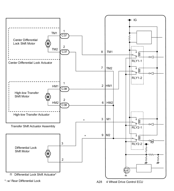
TRANSFER SYSTEM Shift Motor Circuit
WIRING DIAGRAM
CAUTION / NOTICE / HINT
Note
When the vehicle is stopped, mode switching may be unavailable due to the phase of the transfer assembly powertrain. There is no malfunction if mode switching is available after the vehicle is moved.
PROCEDURE
-
CONFIRM PROBLEM SYMPTOM
-
Confirm the problem symptoms.
Result Result Proceed to The 4LO indicator light continues to blink after operation of the transfer position switch (integration control and panel assembly)*1
The 4LO indicator light continues to blink after operation of the transfer position switch*2, *3
A The center differential lock indicator light continues to blink after operation of the center differential lock switch (integration control and panel assembly)*1
The center differential lock indicator light continues to blink after operation of the center differential lock switch*2, *3
B The rear differential lock indicator light continues to blink operation of the differential lock switch*4 C
-
*1: for Automatic Transmission w/ Entry and Start System
-
*2: for Manual Transmission w/ Entry and Start System
-
*3: w/o Entry and Start System
-
*4: w/ Rear Differential Lock
-
Blinking: Blinks at 0.5 second intervals (0.5 seconds on and 0.5 seconds off)
-
B 
INSPECT TRANSFER SHIFT ACTUATOR ASSEMBLY (CENTER DIFFERENTIAL LOCK SHIFT MOTOR) Click here
C
INSPECT DIFFERENTIAL LOCK SHIFT ACTUATOR (DIFFERENTIAL LOCK SHIFT MOTOR) Click here
A 
-
-
INSPECT TRANSFER SHIFT ACTUATOR ASSEMBLY (HIGH-LOW TRANSFER SHIFT MOTOR)
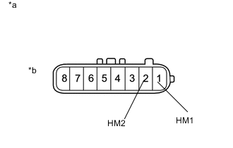
Text in Illustration *a Component without harness connected
(Transfer Shift Actuator Assembly)
*b High-low Transfer Actuator Side
-
Disconnect the C38 transfer shift actuator assembly connector.
-
Measure the resistance according to the value(s) in the table below.
Standard Resistance Tester Connection Condition Specified Condition 1 (HM1) - 2 (HM2) Always 1.5 to 100 Ω
NG 
REPLACE TRANSFER SHIFT ACTUATOR ASSEMBLY Click here
OK
-
-
CHECK HARNESS AND CONNECTOR (4 WHEEL DRIVE CONTROL ECU - TRANSFER SHIFT ACTUATOR ASSEMBLY)
-
Disconnect the A28 4 wheel drive control ECU connector.
-
Disconnect the C38 transfer shift actuator assembly connector.
-
Measure the resistance according to the value(s) in the table below.
Standard Resistance Tester Connection Condition Specified Condition A28-2 (HM1) - C38-1 (HM1) Always Below 1 Ω A28-6 (HM2) - C38-2 (HM2) Always Below 1 Ω A28-2 (HM1) or C38-1 (HM1) - A28-6 (HM2) or C38-2 (HM2) Always 10 kΩ or higher
NG
REPAIR OR REPLACE HARNESS OR CONNECTOR
OK
-
-
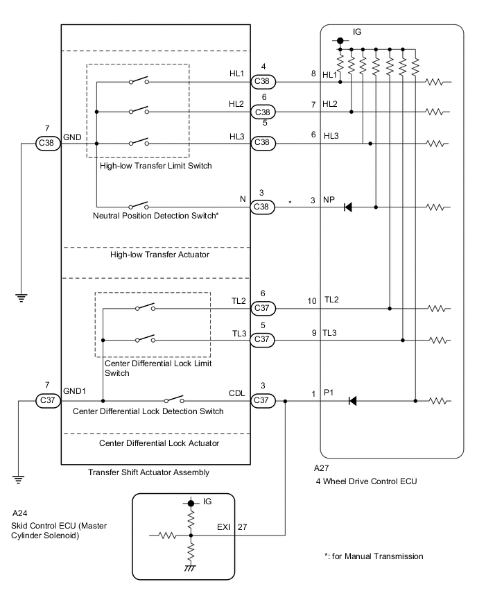
CHECK HARNESS AND CONNECTOR (4 WHEEL DRIVE CONTROL ECU - TRANSFER SHIFT ACTUATOR ASSEMBLY)
-
Disconnect the A27 4 wheel drive control ECU connector.
-
Disconnect the C38 transfer shift actuator assembly connector.
-
Measure the resistance according to the value(s) in the table below.
Standard Resistance Tester Connection Condition Specified Condition A27-8 (HL1) - C38-4 (HL1) Always Below 1 Ω A27-7 (HL2) - C38-6 (HL2) Always Below 1 Ω A27-6 (HL3) - C38-5 (HL3) Always Below 1 Ω A27-3 (NP) - C38-3 (N)* Always Below 1 Ω C38-7 (GND) - Body ground Always Below 1 Ω A27-8 (HL1) or C38-4 (HL1) - Body ground Always 10 kΩ or higher A27-7 (HL2) or C38-6 (HL2) - Body ground Always 10 kΩ or higher A27-6 (HL3) or C38-5 (HL3) - Body ground Always 10 kΩ or higher A27-3 (NP) or C38-3 (N)* - Body ground Always 10 kΩ or higher
-
*: for Manual Transmission
-
NG
REPAIR OR REPLACE HARNESS OR CONNECTOR
OK
-
-
INSPECT TRANSFER SHIFT ACTUATOR ASSEMBLY (LIMIT SWITCH AND DETECTION SWITCH)
-
Turn the ignition switch off.
-
Remove the transfer shift actuator assembly Click here.
-
Check the high-low transfer limit switch and neutral position detection switch* of the transfer shift actuator assembly Click here.
-
*: for Manual Transmission
-
A
REPLACE 4 WHEEL DRIVE CONTROL ECU Click here
B
REPLACE 4 WHEEL DRIVE CONTROL ECU Click here
C
REPLACE TRANSFER SHIFT ACTUATOR ASSEMBLY Click here
-
-
INSPECT TRANSFER SHIFT ACTUATOR ASSEMBLY (CENTER DIFFERENTIAL LOCK SHIFT MOTOR)
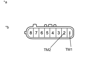
Text in Illustration *a Component without harness connected
(Transfer Shift Actuator Assembly)
*b Center Differential Lock Actuator Side
-
Disconnect the C37 transfer shift actuator assembly connector.
-
Measure the resistance according to the value(s) in the table below.
Standard Resistance Tester Connection Condition Specified Condition 1 (TM1) - 2 (TM2) Always 1.5 to 100 Ω
NG
REPLACE TRANSFER SHIFT ACTUATOR ASSEMBLY Click here
OK
-
-
CHECK HARNESS AND CONNECTOR (4 WHEEL DRIVE CONTROL ECU - TRANSFER SHIFT ACTUATOR ASSEMBLY)
-
Disconnect the A28 4 wheel drive control ECU connector.
-
Disconnect the C37 transfer shift actuator assembly connector.
-
Measure the resistance according to the value(s) in the table below.
Standard Resistance Tester Connection Condition Specified Condition A28-8 (TM1) - C37-1 (TM1) Always Below 1 Ω A28-7 (TM2) - C37-2 (TM2) Always Below 1 Ω A28-8 (TM1) or C37-1 (TM1) - A28-7 (TM2) or C37-2 (TM2) Always 10 kΩ or higher
NG
REPAIR OR REPLACE HARNESS OR CONNECTOR
OK
-
-
CHECK HARNESS AND CONNECTOR (4 WHEEL DRIVE CONTROL ECU - TRANSFER SHIFT ACTUATOR ASSEMBLY)
-
Disconnect the A27 4 wheel drive control ECU connector.
-
Disconnect the C37 transfer shift actuator assembly connector.
-
Disconnect the A24 skid control ECU (master cylinder solenoid) connector.
-
Measure the resistance according to the value(s) in the table below.
Standard Resistance Tester Connection Condition Specified Condition A27-10 (TL2) - C37-6 (TL2) Always Below 1 Ω A27-9 (TL3) - C37-5 (TL3) Always Below 1 Ω A27-1 (P1) - C37-3 (CDL) Always Below 1 Ω C37-7 (GND1) - Body ground Always Below 1 Ω A27-10 (TL2) or C37-6 (TL2) - Body ground Always 10 kΩ or higher A27-9 (TL3) or C37-5 (TL3) - Body ground Always 10 kΩ or higher A27-1 (P1) or C37-3 (CDL) - Body ground Always 10 kΩ or higher
NG
REPAIR OR REPLACE HARNESS OR CONNECTOR
OK
-
-
INSPECT TRANSFER SHIFT ACTUATOR ASSEMBLY (LIMIT SWITCH AND DETECTION SWITCH)
-
Turn the ignition switch off.
-
Remove the transfer shift actuator assembly Click here.
-
Check the center differential lock limit switch and center differential lock detection switch of the transfer shift actuator assembly Click here.
Result Result Proceed to OK for LHD A for RHD B NG C
OK
REPLACE 4 WHEEL DRIVE CONTROL ECU Click here
NG
REPLACE TRANSFER SHIFT ACTUATOR ASSEMBLY Click here
-
-
INSPECT DIFFERENTIAL LOCK SHIFT ACTUATOR (DIFFERENTIAL LOCK SHIFT MOTOR)
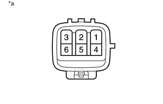
Text in Illustration *a Component without harness connected
(Center Differential Lock Actuator)
-
Disconnect the f1 differential lock shift actuator connector.
-
Measure the resistance according to the value(s) in the table below.
Standard Resistance Tester Connection Condition Specified Condition 3 - 2 Always 1.5 to 100 Ω
NG
REPLACE DIFFERENTIAL LOCK SHIFT ACTUATOR Click here
OK
-
-
CHECK HARNESS AND CONNECTOR (4 WHEEL DRIVE CONTROL ECU - DIFFERENTIAL LOCK SHIFT ACTUATOR)
-
Disconnect the A28 4 wheel drive control ECU connector.
-
Disconnect the f1 differential lock shift actuator connector.
-
Measure the resistance according to the value(s) in the table below.
Standard Resistance Tester Connection Condition Specified Condition A28-3 (M1) - f1-3 Always Below 1 Ω A28-9 (M2) - f1-2 Always Below 1 Ω A28-3 (M1) or f1-3 - A28-9 (M2) or f1-2 Always 10 kΩ or higher
NG
REPAIR OR REPLACE HARNESS OR CONNECTOR
OK
-
-
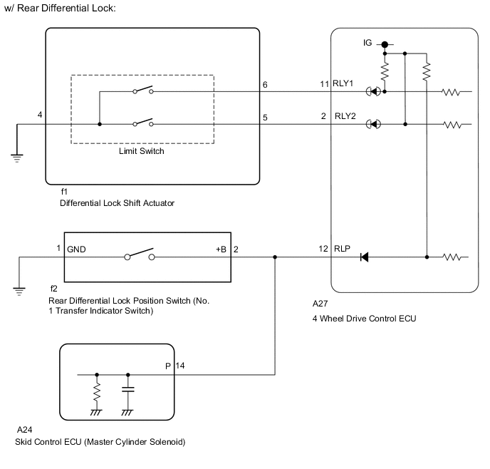
CHECK HARNESS AND CONNECTOR (4 WHEEL DRIVE CONTROL ECU - DIFFERENTIAL LOCK SHIFT ACTUATOR AND NO. 1 TRANSFER INDICATOR SWITCH)
-
Disconnect the A27 4 wheel drive control ECU connector.
-
Disconnect the f1 differential lock shift actuator connector.
-
Disconnect the f2 rear differential lock position switch (No. 1 transfer indicator switch) connector.
-
Disconnect the A24 skid control ECU (master cylinder solenoid) connector.
-
Measure the resistance according to the value(s) in the table below.
Standard Resistance Tester Connection Condition Specified Condition A27-11 (RLY1) - f1-6 Always Below 1 Ω A27-2 (RLY2) - f1-5 Always Below 1 Ω f1-4 - Body ground Always Below 1 Ω A27-12 (RLP) - f2-2 (+B) Always Below 1 Ω f2-1 (GND) - Body ground Always Below 1 Ω A27-11 (RLY1) or f1-6 - Body ground Always 10 kΩ or higher A27-2 (RLY2) or f1-5 - Body ground Always 10 kΩ or higher A27-12 (RLP) or f2-2 (+B) - Body ground Always 10 kΩ or higher
NG
REPAIR OR REPLACE HARNESS OR CONNECTOR
OK
-
-
INSPECT DIFFERENTIAL LOCK SHIFT ACTUATOR (LIMIT SWITCH)
-
Turn the ignition switch off.
-
Remove the differential lock shift actuator Click here.
-
Check the limit switch of the differential lock shift actuator Click here.
NG
REPLACE DIFFERENTIAL LOCK SHIFT ACTUATOR Click here
OK
-
-
INSPECT NO. 1 TRANSFER INDICATOR SWITCH
-
Turn the ignition switch off.
-
Remove the rear differential lock position switch (No. 1 transfer indicator switch) Click here.
-
Check the rear differential lock position switch (No. 1 transfer indicator switch) Click here.
Result Result Proceed to OK for LHD A for RHD B NG C
A
REPLACE 4 WHEEL DRIVE CONTROL ECU Click here
B
REPLACE 4 WHEEL DRIVE CONTROL ECU Click here
C
REPLACE NO. 1 TRANSFER INDICATOR SWITCH Click here
-