PROCEDURE
-
Click here
INSPECT OUTPUT SHAFT
-
Using a dial indicator and 2 V-blocks, measure the shaft runout.
Maximum Runout 0.03 mm (0.00118 in.) If the runout is more than the maximum, replace the output shaft.
-
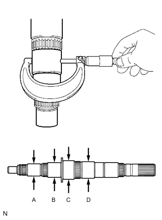
Using a micrometer, measure the journal diameter.
Standard Diameter Part Specified Condition A 37.979 to 37.995 mm (1.4952 to 1.4959 in.) B 45.984 to 46.000 mm (1.8104 to 1.8110 in.) C 57.984 to 58.000 mm (2.2828 to 2.2835 in.) D 49.979 to 49.995 mm (1.9677 to 1.9683 in.) Minimum Diameter Part Specified Condition A 37.979 mm (1.4952 in.) B 45.984 mm (1.8104 in.) C 57.984 mm (2.2828 in.) D 49.979 mm (1.9677 in.) If the diameter is less than the minimum, replace the output shaft.
-
-
Click here
INSPECT 3RD GEAR
-
Using a cylinder gauge, measure the inside diameter of the 3rd gear.
Standard Inside Diameter 44.015 to 44.040 mm (1.733 to 1.734 in.) Maximum Inside Diameter 44.040 mm (1.734 in.) If the inside diameter is more than the maximum, replace the 3rd gear.
-
-
Click here
INSPECT 5TH GEAR
-
Using a cylinder gauge, measure the inside diameter of the 5th gear.
Standard Inside Diameter 53.015 to 53.040 mm (2.087 to 2.088 in.) Maximum Inside Diameter 53.040 mm (2.088 in.) If the inside diameter is more than the maximum, replace the 5th gear.
-
-
Click here
INSPECT 2ND GEAR
-
Using a cylinder gauge, measure the inside diameter of the 2nd gear.
Standard Inside Diameter 65.015 to 65.040 mm (2.560 to 2.561 in.) Maximum Inside Diameter 65.040 mm (2.561 in.) If the inside diameter is more than the maximum, replace the 2nd gear.
-
-
Click here
INSPECT 1ST GEAR
-
Using a cylinder gauge, measure the inside diameter of the 1st gear.
Standard Inside Diameter 57.015 to 57.040 mm (2.2447 to 2.2457 in.) Maximum Inside Diameter 57.040 mm (2.2457 in.) If the inside diameter is more than the maximum, replace the 1st gear.
-
-
Click here
INSPECT NO. 2 TRANSMISSION HUB SLEEVE
-
Check the sliding condition between the No. 2 transmission clutch hub and No. 2 transmission hub sleeve.
-
Check that the spline gear teeth of the No. 2 transmission hub sleeve are not worn.
-
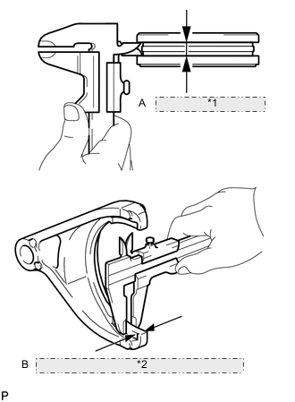
Table 1. *1 12.0 to 12.1 mm (0.472 to 0.476 in.) *2 11.75 to 11.85 mm (0.463 to 0.467 in.) Using a vernier caliper, measure the width of the No. 2 transmission hub sleeve groove (A) and the thickness of the claw part on the gear shift forks (B), and calculate the clearance.
Standard Clearance (A - B) 0.15 to 0.35 mm (0.00591 to 0.0137 in.) Maximum Clearance 0.35 mm (0.0137 in.) If the clearance is is more than the maximum, replace the No. 2 transmission hub sleeve and gear shift fork.
-
-
Click here
INSPECT NO. 3 TRANSMISSION HUB SLEEVE
-
Check the sliding condition between the No. 3 transmission clutch hub and No. 3 transmission hub sleeve.
-
Check that the spline gear teeth of the No. 3 transmission hub sleeve are not worn.
-
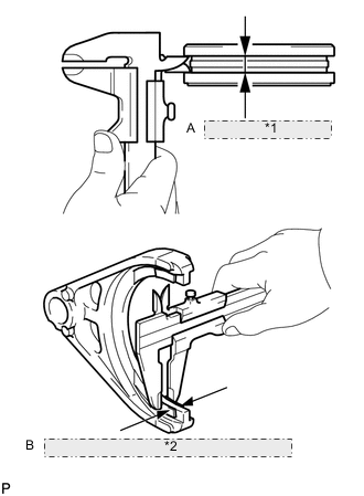
Table 2. *1 10.5 to 10.6 mm (0.413 to 0.417 in.) *2 9.75 to 10.25 mm (0.384 to 0.403 in.) Using a vernier caliper, measure the width of the No. 3 transmission hub sleeve groove (A) and the thickness of the claw part on the gear shift forks (B), and calculate the clearance.
Standard Clearance (A - B) 0.25 to 0.85 mm (0.00984 to 0.0335 in.) Maximum Clearance 0.85 mm (0.0335 in.) If the clearance is more than the maximum, replace the No. 3 transmission hub sleeve and gear shift fork.
-
-
Click here
INSPECT NO. 1 TRANSMISSION HUB SLEEVE
-
Check the sliding condition between the No. 1 transmission clutch hub and No. 1 transmission hub sleeve.
-
Check that the spline gear teeth of the No. 1 transmission hub sleeve are not worn.
-
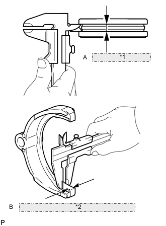
Table 3. *1 12.0 to 12.1 mm (0.472 to 0.476 in.) *2 11.75 to 11.85 mm (0.463 to 0.467 in.) Using a vernier caliper, measure the width of the No. 1 transmission hub sleeve groove (A) and the thickness of the claw part on the gear shift forks (B), and calculate the clearance.
Standard Clearance (A - B) 0.15 to 0.35 mm (0.00591 to 0.0137 in.) Maximum Clearance 0.35 mm (0.0137 in.) If the clearance is more than the maximum, replace the No. 1 transmission hub sleeve and gear shift fork.
-
-
Click here
INSPECT NO. 3 SYNCHRONIZER RING SET (FOR 3RD GEAR)
-
Using a feeler gauge, measure the clearance between the synchronizer ring and the 6th gear.
Standard Clearance 1.15 to 2.05 mm (0.0453 to 0.0807 in.) Minimum Clearance 1.15 mm (0.0453 in.) If the clearance is less than the minimum, replace the synchronizer ring.
-
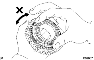
Coat the 3rd gear cone with gear oil. Check the braking effect of the synchronizer ring. Turn the synchronizer ring in one direction while pushing it to the 3rd gear cone. Check that the ring locks.
-
-
Click here
INSPECT NO. 3 SYNCHRONIZER RING (FOR 5TH GEAR)
-
Using a feeler gauge, measure the clearance between the synchronizer ring and the 5th gear.
Standard Clearance 0.80 to 1.60 mm (0.0315 to 0.0629 in.) Minimum Clearance 0.80 mm (0.0315 in.) If the clearance is less than the minimum, replace the synchronizer ring.
-
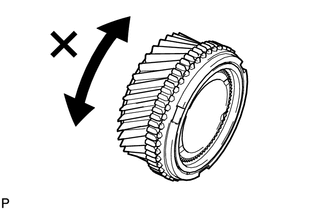
Coat the 5th gear cone with gear oil. Check the braking effect of the synchronizer ring. Turn the synchronizer ring in one direction while pushing it to the 5th gear cone. Check that the ring locks.
-
-
Click here
INSPECT NO. 2 SYNCHRONIZER RING SET (FOR 2ND GEAR)
-
Using a feeler gauge, measure the clearance between the synchronizer ring and 2nd gear.
Standard Clearance 1.23 to 2.13 mm (0.0485 to 0.0838 in.) Minimum Clearance 1.23 mm (0.0485 in.) If the clearance is less than the minimum, replace the synchronizer ring.
-
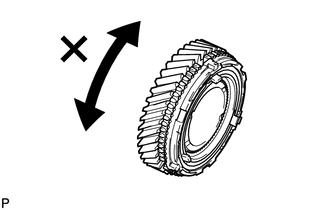
Coat the 2nd gear cone with gear oil. Check the braking effect of the synchronizer ring. Turn the synchronizer ring in one direction while pushing it to the 2nd gear cone. Check that the ring locks.
-
-
Click here
INSPECT NO.1 SYNCHRONIZER RING SET (FOR 1ST GEAR)
-
Using a feeler gauge, measure the clearance between the synchronizer ring and 1st gear.
Standard Clearance 1.25 to 2.15 mm (0.0493 to 0.0846 in.) Minimum Clearance 1.25 mm (0.0493 in.) If the clearance is less than the minimum, replace the synchronizer ring.
-
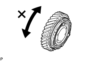
Coat the 1st gear cone with gear oil. Check the braking effect of the synchronizer ring. Turn the synchronizer ring in one direction while pushing it to the 1st gear cone. Check that the ring locks.
-