TRANSFER SYSTEM, Diagnostic DTC:P17AC
| DTC Code | DTC Name |
|---|---|
| P17AC | Transfer Shift Motor Limit Switch Circuit |
DESCRIPTION
When the transfer shift actuator assembly is switching between high (H4) and low (L4), the HL1, HL2 and HL3 terminals are in one of the ON/OFF combinations listed in the table below.
| Terminal | Mode | ||||||
|---|---|---|---|---|---|---|---|
| HIGH (H4) | Switching | LOW (L4) | |||||
| HL1 | ON | ON | ←→ | OFF* | ←→ | OFF | OFF |
| HL2 | OFF | OFF | OFF* | ON | ON | ||
| HL3 | OFF | ON | ON* | ON | OFF | ||
-
*: Neutral position (only for vehicles with a manual transmission)
For vehicles with a manual transmission, when conditions for switching between H4 and L4 are not met, the transfer shift actuator assembly temporarily stops at the neutral position. Afterwards, when the conditions are met, switching is performed.
A malfunction is detected depending on the combination of the 3 circuits that make up the high-low transfer limit switch.
| DTC No. | DTC Detection Condition
|
Trouble Area |
|---|---|---|
| P17AC |
|
|
WIRING DIAGRAM
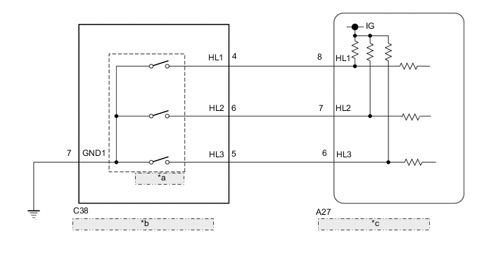
| *a | Limit Switch |
| *b | Transfer Shift Actuator Assembly |
| *c | 4 Wheel Drive Control ECU |
PROCEDURE
-
CHECK HARNESS AND CONNECTOR (4 WHEEL DRIVE CONTROL ECU - TRANSFER SHIFT ACTUATOR ASSEMBLY)
-
Disconnect the A27 4 wheel drive control ECU connector.
-
Disconnect the C38 transfer shift actuator assembly connector.
-
Measure the resistance according to the value(s) in the table below.
Standard Resistance Tester Connection Condition Specified Condition A27-8 (HL1) - C38-4 (HL1) Always Below 1 Ω A27-7 (HL2) - C38-6 (HL2) Always Below 1 Ω A27-6 (HL3) - C38-5 (HL3) Always Below 1 Ω C38-7 (GND) - Body ground Always Below 1 Ω A27-8 (HL1) or C38-4 (HL1) - Body ground Always 10 kΩ or higher A27-7 (HL2) or C38-6 (HL2) - Body ground Always 10 kΩ or higher A27-6 (HL3) or C38-5 (HL3) - Body ground Always 10 kΩ or higher
NG 
REPAIR OR REPLACE HARNESS OR CONNECTOR
OK 
-
-
CHECK 4 WHEEL DRIVE CONTROL ECU (ECU OUTPUT VOLTAGE)
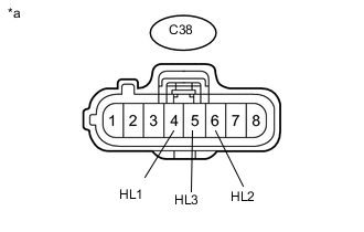
Text in Illustration *a Front view of wire harness connector
(to Transfer Shift Actuator Assembly)
-
Disconnect the C38 transfer shift actuator assembly connector.
-
Measure the voltage according to the value(s) in the table below.
Standard Voltage Tester Connection Switch Condition Specified Condition C38-4 (HL1) - Body ground Ignition switch ON 10 to 14 V C38-6 (HL2) - Body ground Ignition switch ON 10 to 14 V C38-5 (HL3) - Body ground Ignition switch ON 10 to 14 V Result Result Proceed to OK A NG for LHD B for RHD C
A
REPLACE TRANSFER SHIFT ACTUATOR ASSEMBLY Click here
B
REPLACE 4 WHEEL DRIVE CONTROL ECU Click here
C
REPLACE 4 WHEEL DRIVE CONTROL ECU Click here
-