MANUAL TRANSMISSION UNIT REASSEMBLY

PROCEDURE
-
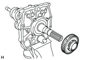
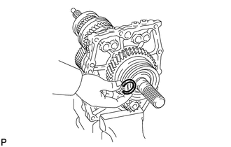
INSTALL OUTPUT SHAFT ASSEMBLY
-
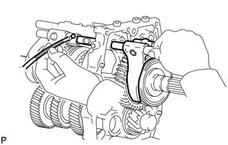
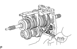
Fix the transmission intermediate plate in a vise between aluminum plates.
Note
Do not overtighten the vise.
-
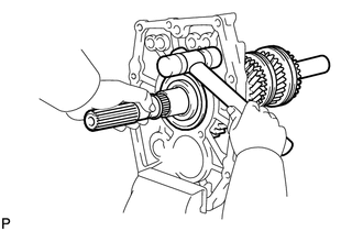
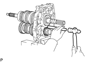
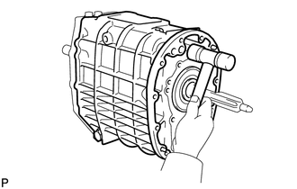
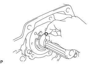
Install the output shaft by lightly tapping on the back side of the intermediate plate with a plastic-faced hammer.
Tech Tips
Perform the procedure while pulling the output shaft assembly to the rear side by hand.
-
-
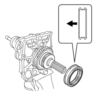
INSTALL OUTPUT SHAFT BEARING SHAFT SNAP RING
-
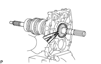
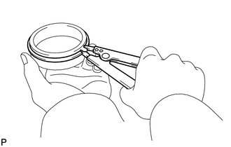
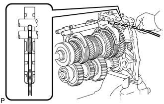
Using a snap ring expander, install the snap ring to the output shaft bearing.
-
-
INSTALL NO. 2 SYNCHRONIZER RING
-
Install the No. 2 synchronizer ring to the input shaft.
-
-
INSTALL INPUT SHAFT ASSEMBLY
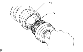
*1 Shifting Key *2 Key Groove
-
Install the input shaft to the output shaft.
Tech Tips
Align the shifting key of the synchronizer ring with the groove of the clutch hub.
-
Install the clutch hub and confirm that the gear and synchronizer ring move smoothly.
-
-
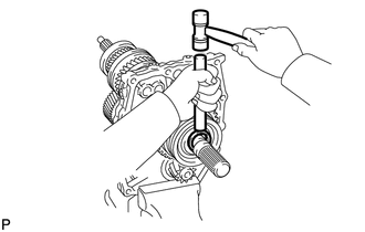
INSTALL COUNTER GEAR
-
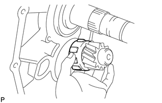
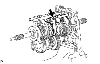
Install the counter gear to the intermediate plate.
-
Install the center bearing to the counter gear.
-
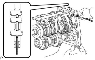
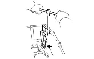
Using a snap ring expander, install the snap ring to the outer race.
-
Using a brass bar and hammer, lightly tap the bearing outer race uniformly to install it.
Note
Do not drop the counter gear. Hold the front side of the counter gear.
-
-
INSTALL OUTPUT SHAFT REAR BEARING(MTM) RETAINER
-
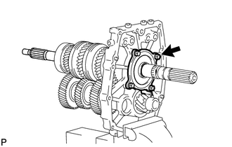
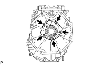
Install the output shaft rear bearing retainer to the intermediate plate with the 4 bolts.
- Torque:
- 18 N*m { 185 kgf*cm, 13 ft.*lbf }
-
-
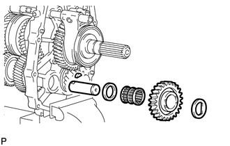
INSTALL REVERSE GEAR BEARING
-
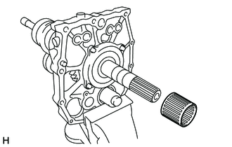
Coat the reverse gear bearing with gear oil, and install it to the output shaft.
-
-
INSTALL REVERSE GEAR
-
Coat the reverse gear with gear oil, and install it to the output shaft.
Tech Tips
Apply gear oil to the inner diameter surface and thrust surface of the reverse gear.
-
-
INSTALL REVERSE SYNCHRONIZER RING SET
-
Apply gear oil to the reverse synchronizer ring set and tapered cone surface of the reverse gear.
-
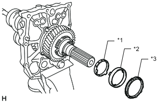
*1 Outer Ring *2 Middle Ring *3 Inner Ring Install the reverse synchronizer ring set to the reverse gear.
Note
-
Align the claw of the middle ring and the cutout of the reverse gear.
-
Align the claw of the inner ring and the key groove of the outer ring.
-
-
-
INSTALL NO. 4 TRANSMISSION CLUTCH HUB
-
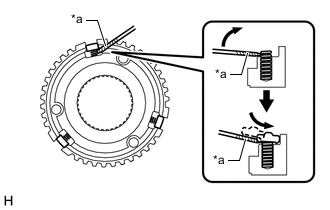
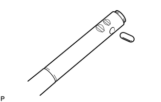
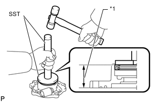
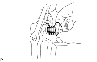
*a Protective Tape Using a screwdriver, install the 3 shifting keys and 3 springs to the No. 4 transmission clutch hub.
Note
Lightly move the shifting key with your finger and check that it does not separate from the No. 4 transmission clutch hub.
Tech Tips
-
Push down the spring as shown in the illustration when installing the shifting key.
-
Tape the screwdriver tip before use.
-
-
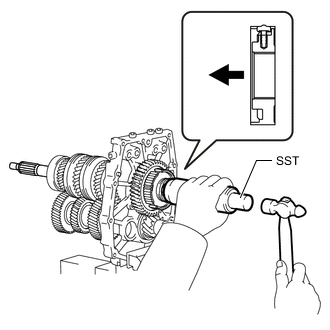

Front Side Using SST and a hammer, install the No. 4 transmission clutch hub.
- SST
- 09316-60011 ( 09316-00011 )
Note
-
Install in the correct direction.
-
Align the key groove of the reverse synchronizer ring set with the shifting key position when installing.
Tech Tips
Align the shifting key of the synchronizer ring with the groove of the clutch hub.
-
Install the clutch hub and confirm that the gear and synchronizer ring move smoothly.
-
-
INSTALL NO. 1 TRANSMISSION HUB SLEEVE
-
Apply a light coat of gear oil to the spline of No. 1 transmission hub sleeve.
-
Front Side Install the No. 1 transmission hub sleeve to the No. 4 transmission clutch hub.
Note
Do not mistake the installation direction of the No. 1 transmission hub sleeve.
-
-
INSTALL NO. 3 TRANSMISSION CLUTCH HUB SHAFT SNAP RING
-
Select a new snap ring that will allow minimum clearance.
Standard Clearance 0.1 mm (0.00393 in.) or less Snap Ring Thickness Part No. Thickness Mark 90520-34018 2.40 to 2.45 mm
(0.0945 to 0.0965 in.)
A 90520-34019 2.45 to 2.50 mm
(0.0965 to 0.0984 in.)
B 90520-34020 2.50 to 2.55 mm
(0.0984 to 0.100 in.)
C 90520-34021 2.55 to 2.60 mm
(0.100 to 0.102 in.)
D 90520-34022 2.60 to 2.65 mm
(0.102 to 0.104 in.)
E 90520-34023 2.65 to 2.70 mm
(0.104 to 0.106 in.)
F -
Using a brass bar and hammer, install the snap ring to the output shaft.
-
-
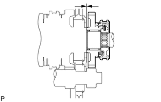
INSPECT REVERSE GEAR THRUST CLEARANCE
-
Using a feeler gauge, measure the reverse gear thrust clearance.
Standard Clearance 0.15 to 0.52 mm (0.00591 to 0.0204 in.) If the clearance is outside the specification, replace the defective gear or shaft.
-
-
INSTALL NO. 2 GEAR SHIFT FORK
-
Install the No. 2 gear shift fork.
-
-
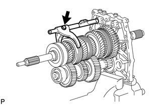
INSTALL NO. 2 GEAR SHIFT FORK SHAFT
-
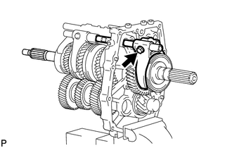
Install the No. 2 gear shift fork shaft to the No. 2 gear shift fork and intermediate plate with the bolt.
- Torque:
- 46 N*m { 472 kgf*cm, 34 ft.*lbf }
-
-
INSTALL NO. 1 GEAR SHIFT FORK
-
Install the No. 1 gear shift fork.
-
-
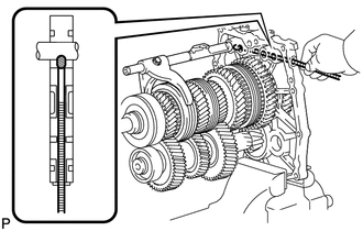
INSTALL NO. 1 GEAR SHIFT FORK SHAFT
-
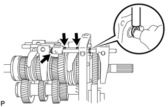
Using a magnet hand, install the interlock pin to the intermediate plate.
-
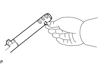
Apply MP grease to the interlock pin.
-
Install the interlock pin to the No. 1 gear shift fork shaft.
-
Install the No. 1 gear shift fork shaft to the No. 2 gear shift fork and intermediate plate with the bolt.
- Torque:
- 46 N*m { 472 kgf*cm, 34 ft.*lbf }
-
-
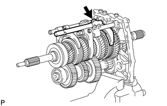
INSTALL NO. 3 GEAR SHIFT FORK
-
Install the No. 3 gear shift fork.
-
-
INSTALL NO. 3 GEAR SHIFT FORK SHAFT
-
Using a magnet hand, install the interlock pin to the intermediate plate.
-
Apply MP grease to the interlock pin.
-
Install the interlock pin to the No. 3 gear shift fork shaft.
-
Install the No. 3 gear shift fork shaft to the No. 3 gear shift fork and intermediate plate with the bolt.
- Torque:
- 46 N*m { 472 kgf*cm, 34 ft.*lbf }
-
-
INSTALL REVERSE SHIFT FORK
-
Install the reverse shift fork.
-
-
INSTALL NO. 4 GEAR SHIFT FORK SHAFT
-
Using a magnet hand, install the ball to the intermediate plate.
-
Using a magnet hand, install the ball to the reverse shift head.
-
Install the No. 4 gear shift fork shaft to the reverse gear shift fork and intermediate plate with the bolt.
- Torque:
- 34 N*m { 350 kgf*cm, 25 ft.*lbf }
-
-
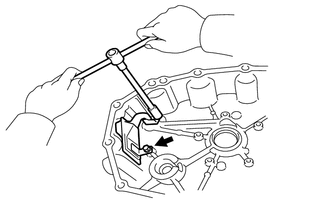
INSTALL SHIFT FORK SHAFT SNAP RING
-
Using a brass bar and hammer, install the 4 snap rings.
-
-
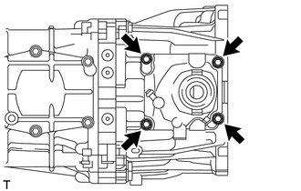
INSTALL SHIFT DETENT BALL PLUG
-
Install the 4 balls and 4 springs to the intermediate plate.
-
Apply adhesive to 2 or 3 threads of the 4 detent ball plugs.
Adhesive Toyota Genuine Adhesive 1324, Three Bond 1324 or equivalent -
Using a T40 "TORX" socket wrench, install the 4 detent ball plugs.
- Torque:
- 19 N*m { 190 kgf*cm, 14 ft.*lbf }
-
-
INSTALL MANUAL TRANSMISSION CASE RECEIVER
-
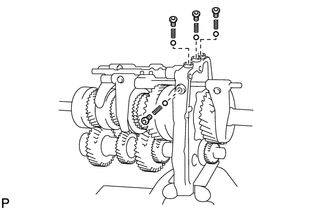
Install the transmission case receiver to the intermediate plate with the 3 bolts.
- Torque:
- 18 N*m { 185 kgf*cm, 13 ft.*lbf }
-
-
INSTALL INTERMEDIATE PLATE STRAIGHT PIN
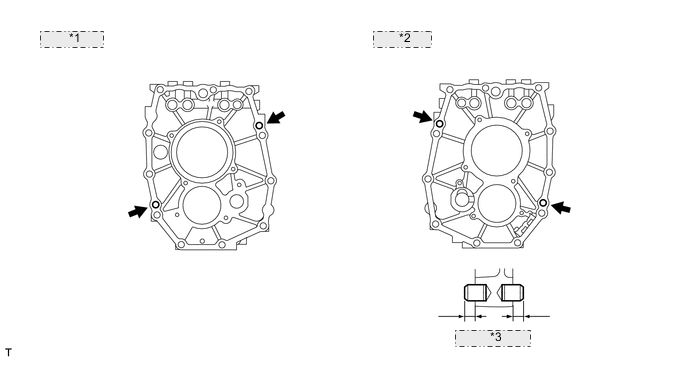
*1 Front Side: *2 Rear Side: *3 7.0 to 9.0 mm
-
Using a plastic-faced hammer, tap 4 new straight pins into the intermediate plate.
Standard Protrusion Height 7.0 to 9.0 mm (0.276 to 0.354 in.)
-
-
INSTALL TRANSFER ADAPTER STRAIGHT PIN
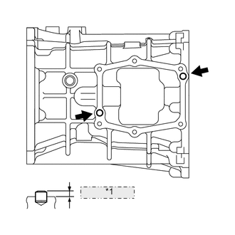
Upper Side *1 4.0 to 6.0 mm
-
Using a plastic-faced hammer, tap 2 new straight pins into the transmission case.
Standard Protrusion Height 4.0 to 6.0 mm (0.158 to 0.236 in.) -
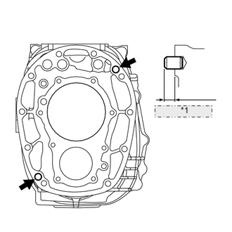
Front Side *1 9.0 to 11.0 mm Using a plastic-faced hammer, tap 2 new straight pins into the transmission case.
Standard Protrusion Height 9.0 to 11.0 mm (0.355 to 0.433 in.)
-
-
INSTALL NO. 1 OIL RECEIVER PIPE (MTM)
-
Install the oil receiver pipe to the transmission case with the 2 bolts.
- Torque:
- 12 N*m { 120 kgf*cm, 9 ft.*lbf }
-
-
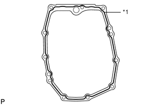
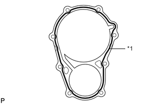
INSTALL MANUAL TRANSMISSION CASE SUB-ASSEMBLY
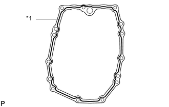
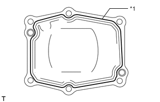
*1 Seal Packing
-
Apply seal packing to the transmission case, as shown in the illustration.
Seal Packing Toyota Genuine Seal Packing 1281, Three Bond 1281 or equivalent Note
Parts must be assembled within 10 minutes of application. Otherwise, the packing (FIPG) material must be removed and reapplied.
-
Install the transmission case by lightly tapping it into place with a plastic-faced hammer.
Note
Make sure that the oil receiver installed on the transmission side is above the oil application area of the intermediate plate side oil receiver.
-
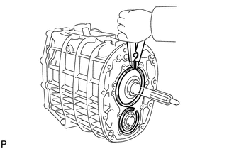
Using a snap ring expander, install the 2 snap rings to the counter gear and input shaft.
-
-
INSTALL REVERSE IDLER GEAR SHAFT WOODRUFF KEY
-
Install the woodruff key to the reverse idler gear shaft.
-
-
INSTALL REVERSE IDLER GEAR SHAFT
-
Install the reverse idler gear shaft to the intermediate plate.
-
-
INSTALL REVERSE IDLER THRUST WASHER
-
Install the thrust washer to the reverse idler gear shaft.
Note
-
Align the protrusion of the washer with the groove of the intermediate plate during installation.
-
Install the washer so that the dimpled surface of the washer contacts the reverse idler gear thrust surface.
-
-
-
INSTALL REVERSE IDLER GEAR BUSH OR BEARING
-
Install the bearing to the reverse idler gear shaft.
-
-
INSTALL REVERSE IDLER GEAR
-
Install the reverse idler gear to the reverse idler gear shaft.
-
-
INSTALL NO. 2 REVERSE IDLER THRUST WASHER
-
Install the thrust washer to the reverse idler gear shaft.
Note
Install the washer so that the dimpled surface of the washer contacts the reverse idler gear thrust surface.
-
-
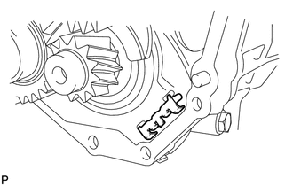
INSTALL TRANSMISSION MAGNET
-
Install the transmission magnet to the intermediate plate.
-
-
INSTALL MANUAL TRANSMISSION OIL STRAINER SUB-ASSEMBLY
-
Install a new O-ring to the oil strainer.
-
Apply a light coat of gear oil to the O-ring.
-
Install the oil strainer to the transfer adapter with the 2 bolts.
- Torque:
- 12 N*m { 120 kgf*cm, 9 ft.*lbf }
-
-
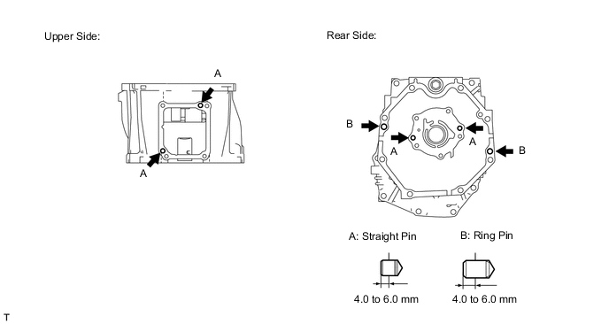
INSTALL TRANSFER ADAPTER STRAIGHT PIN AND RING PIN
-
Using a plastic-faced hammer, tap in 4 new straight pins and 2 new ring pins to the transfer adapter.
Standard Protrusion Height A (Straight Pin) 4.0 to 6.0 mm (0.157 to 0.236 in.) Standard Protrusion Height B (Ring Pin) 4.0 to 6.0 mm (0.157 to 0.236 in.)
-
-
INSTALL TRANSFER ADAPTER SUB-ASSEMBLY
*1 Seal Packing
-
Apply seal packing to the transfer adapter, as shown in the illustration.
Seal Packing Toyota Genuine Seal Packing 1281, Three Bond 1281 or equivalent Note
Parts must be assembled within 10 minutes of application. Otherwise, the packing (FIPG) material must be removed and reapplied.
-
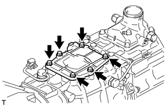
*1 Bracket Install the transfer adapter and bracket to the transmission case with the 11 bolts.
- Torque:
- 37 N*m { 380 kgf*cm, 27 ft.*lbf }
Bolt Length Item Length Bolt A 110 mm (4.33 in.) Bolt B 70 mm (2.75 in.)
-
-
INSTALL TRANSFER ADAPTER PLUG
-
Using a T40 "TORX" socket wrench, install the transfer adapter plug to the transfer adapter.
- Torque:
- 19 N*m { 190 kgf*cm, 14 ft.*lbf }
-
-
INSTALL SHIFT AND SELECT LEVER SHAFT
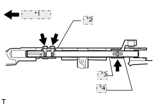
*1 Front Side *2 Shift And Select Lever *3 Shift And Select Lever Shaft *4 Shift Lever Housing
-
Install the shift and select lever, shift lever housing, and shift and select lever shaft to the transmission as shown in the illustration.
-
Install the 2 bolts to the shift and select lever.
- Torque:
- 38 N*m { 390 kgf*cm, 28 ft.*lbf }
-
Install the bolt to the shift lever housing.
- Torque:
- 38 N*m { 390 kgf*cm, 28 ft.*lbf }
-
Using a 14 mm hexagon wrench, install the interlock hole plug to the transfer adapter.
- Torque:
- 18 N*m { 185 kgf*cm, 13 ft.*lbf }
-
-
INSTALL TRANSMISSION FRONT BEARING RETAINER OIL SEAL
-
Using SST and a press, drive in a new oil seal.
- SST
- 09950-60010 ( 09951-00460 )
- 09950-70010 ( 09951-07150 )
Standard Drive in Depth 15.4 to 16.2 mm (0.607 to 0.637 in.) -
Apply gear oil to the lip of the oil seal.
-
-
INSTALL FRONT BEARING RETAINER (MTM)
*1 Seal Packing
-
Apply seal packing to the front bearing retainer, as shown in the illustration.
Seal Packing Toyota Genuine Seal Packing 1281, Three Bond 1281 or equivalent Note
Parts must be assembled within 10 minutes of application. Otherwise, the packing (FIPG) material must be removed and reapplied.
-
Apply adhesive to 2 or 3 threads of the bolts.
Adhesive Toyota Genuine Adhesive 1324, Three Bond 1324 or equivalent -
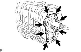
Install the front bearing retainer to the transmission case with the 8 bolts.
- Torque:
- 17 N*m { 170 kgf*cm, 12 ft.*lbf }
-
-
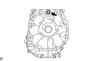
INSTALL TRANSMISSION OIL PUMP COVER OIL SEAL
*1 Dimension A
-
Using SST and a hammer, tap a new oil seal into the oil pump cover in accordance with the dimension specified in the illustration.
- SST
- 09950-70010 ( 09951-07150 )
- 09950-60010 ( 09951-00640 )
-
-
INSTALL TRANSMISSION OIL PUMP COVER
-
Apply MP grease to the straight pins.
-
Install the 2 straight pins.
-
Install a new O-ring to the oil pump cover.
-
Align the oil pump drive rotor groove with the straight pin, and install the oil pump cover to the transfer adapter.
-
Apply adhesive to 2 or 3 threads of the bolts.
Adhesive Toyota Genuine Adhesive 1324, Three Bond 1324 or equivalent -
Install the oil pump cover to the transfer adapter with the 5 bolts.
- Torque:
- 17 N*m { 170 kgf*cm, 12 ft.*lbf }
-
-
INSTALL NO. 1 REVERSE RESTRICT PIN
-
Install the No. 1 reverse restrict pin and spring to the shift lever retainer.
-
Using a 5 mm pin punch and hammer, tap a new slotted pin into the shift lever retainer.
-
-
INSTALL FLOOR SHIFT CONTROL SHIFT LEVER RETAINER SUB-ASSEMBLY
*1 Seal Packing
-
Apply seal packing to the shift lever retainer, as shown in the illustration.
Seal Packing Toyota Genuine Seal Packing 1281, Three Bond 1281 or equivalent Note
Parts must be assembled within 10 minutes of application. Otherwise, the packing (FIPG) material must be removed and reapplied.
-
Apply adhesive to 2 or 3 threads of the bolts.
Adhesive Toyota Genuine Adhesive 1324, Three Bond 1324 or equivalent -
Install the shift lever retainer to the transfer adapter with the 4 bolts.
- Torque:
- 17 N*m { 170 kgf*cm, 12 ft.*lbf }
-
-
INSTALL REVERSE RESTRICT PIN ASSEMBLY
-
Apply adhesive to 2 or 3 threads of the reverse restrict pins.
Adhesive Toyota Genuine Adhesive 1324, Three Bond 1324 or equivalent -
Install the 2 reverse restrict pins to the shift lever retainer.
- Torque:
- 37 N*m { 380 kgf*cm, 27 ft.*lbf }
-
-
INSTALL CONTROL SHAFT COVER
*1 Seal Packing
-
Apply seal packing to the control shaft cover, as shown in the illustration.
Seal Packing Toyota Genuine Seal Packing 1281, Three Bond 1281 or equivalent Note
Parts must be assembled within 10 minutes of application. Otherwise, the packing (FIPG) material must be removed and reapplied.
-
Apply adhesive to 2 or 3 threads of the bolts.
Adhesive Toyota Genuine Adhesive 1324, Three Bond 1324 or equivalent -
Install the control shaft cover to the manual transmission with the 6 bolts.
- Torque:
- 17 N*m { 170 kgf*cm, 12 ft.*lbf }
-
-
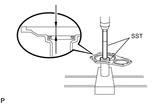
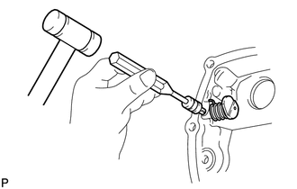
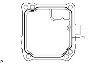
INSTALL SHIFT POSITION SWITCH (for 1VD-FTV)
-
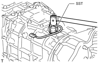
Using SST, install a new gasket and the shift position switch to the transmission.
- SST
- 09817-16011
- Torque:
- 44 N*m { 450 kgf*cm, 33 ft.*lbf }
-
Connect the wire harness clamp.
-
-
INSTALL BACK-UP LIGHT SWITCH ASSEMBLY
-
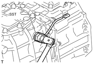
Using SST, install a new gasket and the back-up light switch to the transmission.
- SST
- 09817-16011
- Torque:
- 44 N*m { 450 kgf*cm, 33 ft.*lbf }
-
Connect the wire harness clamp.
-
-
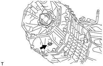
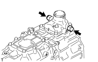
INSTALL MANUAL TRANSMISSION CASE PLUG
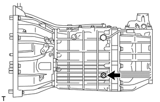
-
Using a T55 "TORX" socket wrench, install a new gasket and the manual transmission case plug to the transmission.
- Torque:
- 37 N*m { 380 kgf*cm, 27 ft.*lbf }
-
-
INSTALL DRAIN PLUG
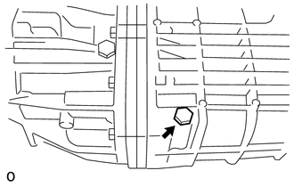
-
Install a new gasket and the drain plug to the manual transmission.
- Torque:
- 37 N*m { 380 kgf*cm, 27 ft.*lbf }
-
-
TEMPORARILY INSTALL FILLER PLUG
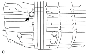
-
Temporarily install a new gasket and the filler plug to the manual transmission.
- Torque:
- 37 N*m { 380 kgf*cm, 27 ft.*lbf }
Tech Tips
The filler plug will be tightened to a torque specification in the "Inspect Transmission Oil" procedure.
-
-
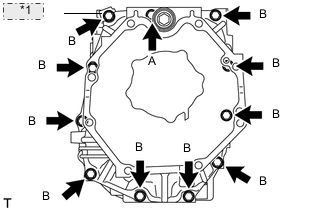
INSTALL CLUTCH HOUSING
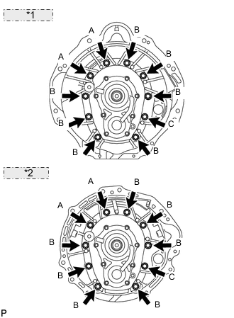
*1 for 1VD-FTV: *2 for 1GR-FE:
-
Apply adhesive to 2 or 3 threads of the bolts labeled A only.
Adhesive Toyota Genuine Adhesive 1324, Three Bond 1324 or equivalent -
Install the clutch housing with the 10 bolts.
- Torque:
- 37 N*m { 380 kgf*cm, 27 ft.*lbf }
Bolt Length Item Length Bolt A 45 mm (1.77 in.) Bolt B 45 mm (1.77 in.) Bolt C 35 mm (1.38 in.)
-
-
INSTALL TRANSMISSION BREATHER SUB-ASSEMBLY (for 1VD-FTV)
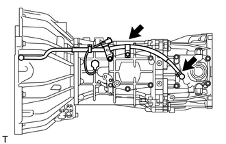
-
Connect the breather hose with the clamp.
-
Install the wire harness clamp.
-
-
INSTALL TRANSMISSION BREATHER SUB-ASSEMBLY (for 1GR-FE)
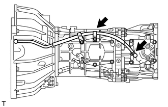
-
Connect the breather hose with the clamp.
-