MANUAL TRANSMISSION ASSEMBLY INSTALLATION
PROCEDURE
-
INSTALL CLUTCH RELEASE FORK SUB-ASSEMBLY
-
INSTALL TRANSFER ASSEMBLY
-
INSTALL MANUAL TRANSMISSION WITH TRANSFER (for 1GR-FE)
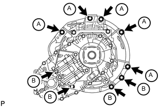
Note
Check that the 2 straight pins are attached to the engine side.
-
Install the manual transmission with transfer with the 9 bolts.
- Torque:
- for bolt A
- 72 N*m { 730 kgf*cm, 53 ft.*lbf }
- for bolt B
- 37 N*m { 380 kgf*cm, 28 ft.*lbf }
Bolt Length Item Length Bolt A 50 mm (1.97 in.) Bolt B 45 mm (1.77 in.)
-
-
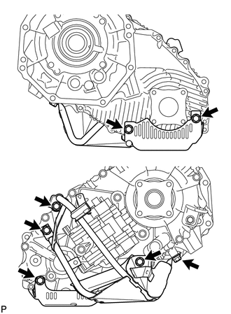
INSTALL MANUAL TRANSMISSION WITH TRANSFER (for 1VD-FTV)
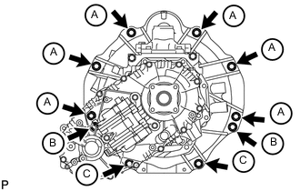
Note
Check that the 2 straight pins are attached to the engine side.
-
Install the manual transmission with transfer with the 10 bolts.
- Torque:
- for bolt A and B
- 72 N*m { 730 kgf*cm, 53 ft.*lbf }
- for bolt C
- 39 N*m { 400 kgf*cm, 29 ft.*lbf }
Bolt Length Item Length Bolt A 45 mm (1.77 in.) Bolt B 50 mm (1.97 in.) Bolt C 70 mm (2.76 in.)
-
-
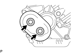
INSTALL OIL PAN COVER (for 1VD-FTV)
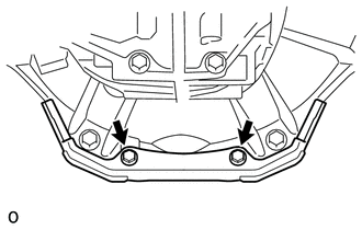
-
Install the oil pan cover with the 2 bolts.
- Torque:
- 21 N*m { 214 kgf*cm, 15 ft.*lbf }
-
-
INSTALL CLUTCH RELEASE CYLINDER TO FLEXIBLE HOSE TUBE
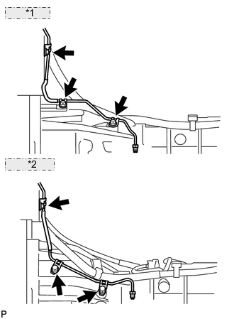
*1 for 1GR-FE: *2 for 1VD-FTV:
-
Install the flexible hose tube with the 3 bolts.
- Torque:
- 20 N*m { 204 kgf*cm, 15 ft.*lbf }
-
-
INSTALL CLUTCH RELEASE CYLINDER ASSEMBLY
-
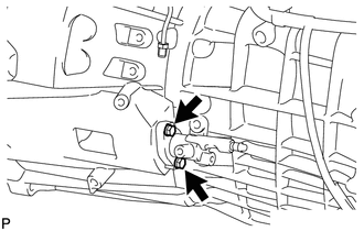
Install the clutch release cylinder with the 2 bolts.
- Torque:
- 12 N*m { 120 kgf*cm, 9 ft.*lbf }
-
-
INSTALL CLUTCH ACCUMULATOR ASSEMBLY
-
INSTALL CLUTCH RELEASE CYLINDER TO ACCUMULATOR TUBE
-
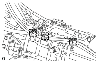
INSTALL NO. 1 CLUTCH HOUSING COVER
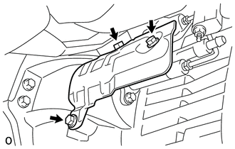
-
Install the housing cover with the 3 bolts.
- Torque:
- 12 N*m { 120 kgf*cm, 9 ft.*lbf }
-
-
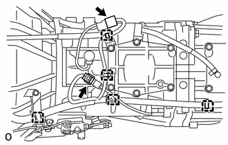
CONNECT WIRE HARNESS (for 1GR-FE)
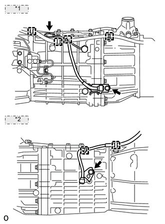
*1 LH Side: *2 RH Side:
-
Connect the 6 clamps.
-
Connect the back-up light switch connector.
-
Install the 2 bolts.
- Torque:
- for LH side
- 29 N*m { 296 kgf*cm, 21 ft.*lbf }
- for RH side
- 60 N*m { 612 kgf*cm, 44 ft.*lbf }
-
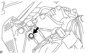
Connect the ground cable with the bolt.
- Torque:
- 8.0 N*m { 82 kgf*cm, 71 in.*lbf }
-
Connect the 2 connectors and 3 clamps.
-
-
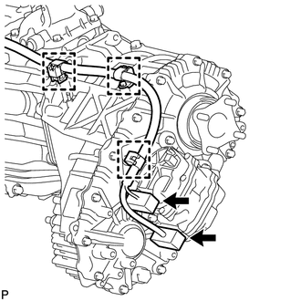
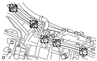
CONNECT WIRE HARNESS (for 1VD-FTV)
-
Connect the 5 clamps.
-
Connect the back-up light switch connector.
-
Connect the shift position switch connector.
-
Connect the ground cable with the bolt.
- Torque:
- 8.0 N*m { 82 kgf*cm, 71 in.*lbf }
-
Connect the 2 connectors and 3 clamps.
-
-
INSTALL TRANSFER BREATHER HOSE SUB-ASSEMBLY (for 1GR-FE)
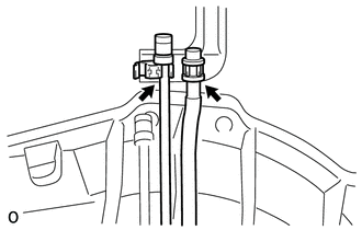
-
Connect the 2 breather hoses to the bracket.
-
Connect the 5 clamps.
-
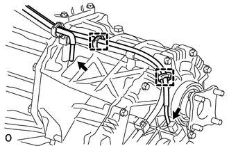
Connect the breather hose to the transfer and actuator, and attach the 2 clamps.
-
-
INSTALL TRANSFER BREATHER HOSE SUB-ASSEMBLY (for 1VD-FTV)
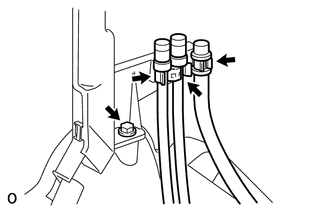
-
Install the bracket with the bolt.
-
Connect the 3 breather hoses to the bracket.
-
Connect the 3 clamps.
-
Connect the breather hose to the transfer and actuator, and attach the 2 clamps.
-
-
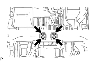
INSTALL REAR NO. 1 ENGINE MOUNTING INSULATOR
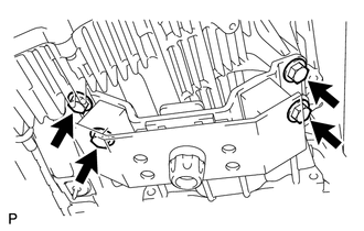
-
Install the engine mounting insulator to the transmission with the 4 bolts.
- Torque:
- 59 N*m { 602 kgf*cm, 44 ft.*lbf }
-
-
INSTALL NO. 2 FRAME CROSSMEMBER SUB-ASSEMBLY
-
Install the frame crossmember to the rear engine mounting insulator with the 4 bolts.
- Torque:
- 37 N*m { 377 kgf*cm, 27 ft.*lbf }
-
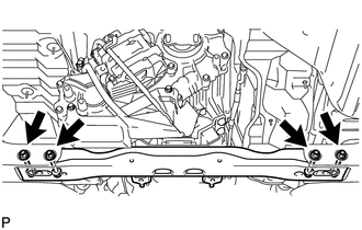
Install the frame crossmember to the vehicle body with the 4 bolts, 4 washers and 4 nuts.
T = 110 N*m{ 1,122 kgf*cm 81 ft.*lbf }
-
-
INSTALL STARTER ASSEMBLY (for 1GR-FE)
-
INSTALL NO. 2 MANIFOLD STAY (for 1GR-FE)
-
INSTALL MANIFOLD STAY (for 1GR-FE)
-
INSTALL EXHAUST PIPE (for 1GR-FE)
-
INSTALL EXHAUST PIPE (for 1VD-FTV)
w/o DPF: Click here
w/ DPF: Click here
-
INSTALL FRONT PROPELLER SHAFT ASSEMBLY
-
INSTALL PROPELLER SHAFT ASSEMBLY
-
ADD MANUAL TRANSMISSION OIL
-
INSPECT TRANSMISSION OIL
-
INSTALL LOWER TRANSFER CASE PROTECTOR
-
Install the lower transfer case protector with the 7 bolts.
- Torque:
- 14 N*m { 139 kgf*cm, 10 ft.*lbf }
-
-
INSTALL TRANSFER DYNAMIC DAMPER (for 1VD-FTV)
-
Install the transfer dynamic damper with the 2 bolts.
- Torque:
- 12 N*m { 122 kgf*cm, 9 ft.*lbf }
-
-
INSTALL TRANSFER HEAT INSULATOR
-
INSTALL TUBE CONNECTOR TO FLEXIBLE HOSE TUBE (for 1VD-FTV)
-
INSTALL AIR TUBE SUB-ASSEMBLY LH (for 1VD-FTV)
-
INSTALL CLUTCH HOSE (for 1VD-FTV)
-
INSTALL NO. 2 COOL AIR INLET (w/o Intercooler)
-
INSTALL INTERCOOLER ASSEMBLY (w/ Intercooler)
-
INSTALL NO. 1 ENGINE COVER SUB-ASSEMBLY
-
INSTALL FLOOR SHIFT LEVER ASSEMBLY
-
Apply MP grease to the tip of the shift lever.
-
Cover the shift lever cap with a cloth.
-
Press down on the shift lever cap and rotate it clockwise to install it.
-
-
INSTALL SHIFT LEVER BOOT ASSEMBLY
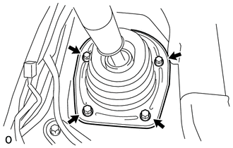
-
Install the shift lever retainer and shift lever boot with the 4 screws.
-
-
INSTALL UPPER CONSOLE PANEL SUB-ASSEMBLY
w/o Console Box Lid Click here
w/ Cool Box Click here
w/o Cool Box Click here
-
FILL RESERVOIR WITH BRAKE FLUID
-
BLEED CLUTCH LINE
-
CHECK FLUID LEVEL IN RESERVOIR
-
INSPECT FOR CLUTCH FLUID LEAK
-
CONNECT CABLE TO NEGATIVE BATTERY TERMINAL
Note
When disconnecting the cable, some systems need to be initialized after the cable is reconnected Click here.