TRANSFER SYSTEM, Diagnostic DTC:P17D0
| DTC Code | DTC Name |
|---|---|
| P17D0 | Center Differential Lock Control SW Circuit |
DESCRIPTION
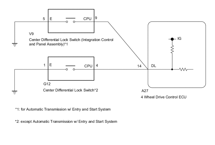
This DTC is output when a malfunction is detected in the center differential lock switch (integration control and panel assembly)*1 or center differential lock switch*2.
| DTC No. | DTC Detection Condition
|
Trouble Area |
|---|---|---|
| P17D0 |
|
|
-
*1: for Automatic Transmission w/ Entry and Start System
-
*2: except Automatic Transmission w/ Entry and Start System
WIRING DIAGRAM
PROCEDURE
-
CHECK HARNESS AND CONNECTOR (4 WHEEL DRIVE CONTROL ECU - CENTER DIFFERENTIAL LOCK SWITCH)
-
Disconnect the A27 4 wheel drive control ECU connector.
-
for Automatic Transmission w/ Entry and Start System:
Disconnect the V9 center differential lock switch (integration control and panel assembly) connector.
-
except Automatic Transmission w/ Entry and Start System:
Disconnect the G12 center differential lock switch connector.
-
Measure the resistance according to the value(s) in the table below.
Standard Resistance for Automatic Transmission w/ Entry and Start System: Tester Connection Condition Specified Condition A27-14 (DL) - V9-9 (CPU) Always Below 1 Ω V9-5 (E) - Body ground Always Below 1 Ω A27-14 (DL) or V9-9 (CPU) - Body ground Always 10 kΩ or higher except Automatic Transmission w/ Entry and Start System: Tester Connection Condition Specified Condition A27-14 (DL) - G12-4 (CPU) Always Below 1 Ω G12-1 (E) - Body ground Always Below 1 Ω A27-14 (DL) or G12-4 (CPU) - Body ground Always 10 kΩ or higher
NG 
REPAIR OR REPLACE HARNESS OR CONNECTOR
OK 
-
-
INSPECT INTEGRATION CONTROL AND PANEL ASSEMBLY OR CENTER DIFFERENTIAL LOCK SWITCH
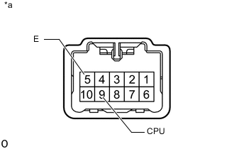
Text in Illustration *a Component without harness connected
(Center Differential Lock Switch (Integration Control and Panel Assembly))
-
for Automatic Transmission w/ Entry and Start System:
Disconnect the V9 center differential lock switch (integration control and panel assembly) connector.
-
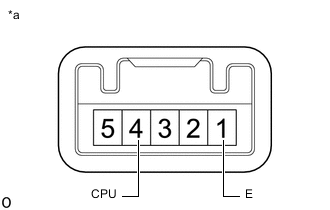
Text in Illustration *a Component without harness connected
(Center Differential Lock Switch)
Measure the resistance according to the value(s) in the table below.
Standard Resistance Tester Connection Condition Specified Condition 9 (CPU) - 5 (E) Switch not pressed 10 kΩ or higher -
except Automatic Transmission w/ Entry and Start System:
Disconnect the G12 center differential lock switch connector.
-
Measure the resistance according to the value(s) in the table below.
Standard Resistance Tester Connection Condition Specified Condition 4 (CPU) - 1 (E) Switch not pressed 10 kΩ or higher Result Result Proceed to OK for LHD A for RHD B NG for Automatic Transmission w/ Entry and Start System C for Manual Transmission w/ Entry and Start System D w/o Entry and Start System E
A
REPLACE 4 WHEEL DRIVE CONTROL ECU Click here
B
REPLACE 4 WHEEL DRIVE CONTROL ECU Click here
C
REPLACE INTEGRATION CONTROL & PANEL ASSEMBLY Click here
D
REPLACE CENTER DIFFERENTIAL LOCK SWITCH Click here
E
REPLACE CENTER DIFFERENTIAL LOCK SWITCH Click here
-