TRANSFER SYSTEM, Diagnostic DTC:P17DF
| DTC Code | DTC Name |
|---|---|
| P17DF | Center Differential Lock Limit SW Circuit |
DESCRIPTION
When the transfer shift actuator assembly is switching between free and lock, the TL2 and TL3 terminals are in one of the ON/OFF combinations listed in the table below.
| Terminal | Mode | ||
|---|---|---|---|
| FREE | Switching | LOCK | |
| TL2 | OFF | ON | ON |
| TL3 | ON | ON | OFF |
A malfunction is detected depending on the combination of the 2 circuits that make up the center differential lock limit switch.
| DTC No. | DTC Detection Condition
|
Trouble Area |
|---|---|---|
| P17DF |
|
|
WIRING DIAGRAM
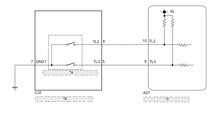
| *a | Center Differential Lock Limit Switch |
| *b | Transfer Shift Actuator Assembly |
| *c | 4 Wheel Drive Control ECU |
PROCEDURE
-
CHECK HARNESS AND CONNECTOR (4 WHEEL DRIVE CONTROL ECU - TRANSFERSHIFT ACTUATOR ASSEMBLY)
-
Disconnect the A27 4 wheel drive control ECU connector.
-
Disconnect the C37 transfer shift actuator assembly connector.
-
Measure the resistance according to the value(s) in the table below.
Standard Resistance Tester Connection Condition Specified Condition A27-10 (TL2) - C37-6 (TL2) Always Below 1 Ω A27-9 (TL3) - C37-5 (TL3) Always Below 1 Ω C37-7 (GND1) - Body ground Always Below 1 Ω A27-10 (TL2) or C37-6 (TL2) - Body ground Always 10 kΩ or higher A27-9 (TL3) or C37-5 (TL3) - Body ground Always 10 kΩ or higher
NG 
REPAIR OR REPLACE HARNESS OR CONNECTOR
OK 
-
-
CHECK 4 WHEEL DRIVE CONTROL ECU (ECU OUTPUT VOLTAGE)
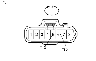
Text in Illustration *a Front view of wire harness connector
(to Transfer Shift Actuator Assembly)
-
Disconnect the C37 transfer shift actuator assembly connector.
-
Measure the voltage according to the value(s) in the table below.
Standard Voltage Tester Connection Switch Condition Specified Condition C37-6 (TL2) - Body ground Ignition switch ON 10 to 14 V C37-5 (TL3) - Body ground Ignition switch ON 10 to 14 V Result Result Proceed to OK for LHD A for RHD B NG C
A
REPLACE 4 WHEEL DRIVE CONTROL ECU Click here
B
REPLACE 4 WHEEL DRIVE CONTROL ECU Click here
C
REPLACE TRANSFER SHIFT ACTUATOR ASSEMBLY Click here
-