AUTOMATIC TRANSMISSION UNIT REASSEMBLY

PROCEDURE
-
BEARING POSITION
-
Check each bearing position and installation direction.
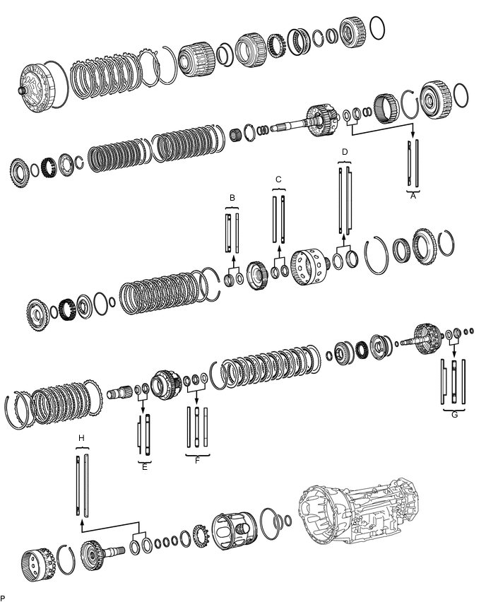
Bearing Position Position Front Race Diameter
Inside/Outside
Thrust Bearing Diameter
Inside/Outside
Rear Race Diameter
Inside/Outside
A - 36.2 mm (1.425 in.) / 58.2 mm (2.291 in.) 44.0 mm (1.732 in.) / 62.0 mm (2.441 in.) B - 34.5 mm (1.358 in.) / 49.9 mm (1.965 in.) 36.6 mm (1.441 in.) / 51.9 mm (2.043 in.) C 46.5 mm (1.831 in.) / 60.1 mm (2.366 in.) 47.0 mm (1.850 in.) / 61.9 mm (2.437 in.) - D - 71.2 mm (2.803 in.) / 84.5 mm (3.327 in.) 71.9 mm (2.831 in.) / 87.8 mm (3.457 in.) E 30.0 mm (1.181 in.) / 49.9 mm (1.965 in.) 31.0 mm (1.221 in.) / 53.7 mm (2.112 in.) - F 31.5 mm (1.240 in.) / 57.3 mm (2.256 in.) 28.7 mm (1.130 in.) / 53.8 mm (2.118 in.) 28.7 mm (1.130 in.) / 53.5 mm (2.106 in.) G 26.2 mm (1.031 in.) / 52.7 mm (2.075 in.) 29.3 mm (1.154 in.) / 51.2 mm (2.016 in.) 29.3 mm (1.154 in.) / 54.0 mm (2.126 in.) H - 58.9 mm (2.319 in.) / 76.7 mm (3.020 in.) 62.0 mm (2.441 in.) / 82.5 mm (3.248 in.)
-
-
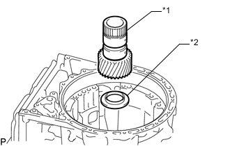
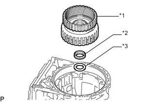
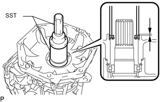
INSTALL OUTPUT SHAFT REAR RADIAL BALL BEARING
-
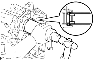
Using SST, tap in a new output shaft rear radial ball bearing to the automatic transmission case sub-assembly.
- SST
- 09316-60011 ( 09316-00011, 09316-00021 )
Tech Tips
Install the output shaft rear radial ball bearing so that there is no clearance between the output shaft rear radial ball bearing and the automatic transmission case sub-assembly.
-
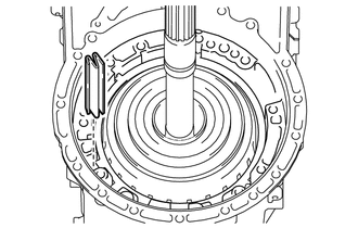
Using needle-nose pliers, install the snap ring.
-
-
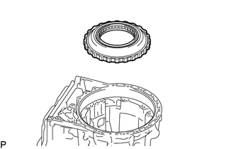
INSTALL 1ST AND REVERSE BRAKE PLATE STOPPER SPRING
-
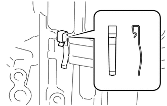
Install the 1st and reverse brake plate stopper spring to the automatic transmission case sub-assembly.
Note
The shapes of the parts are different. Refer to the illustration when installing the parts.
-
-
INSTALL NO. 2 BRAKE PISTON
-
Coat 3 new O-rings with ATF, and install them to the No. 2 brake piston.
-
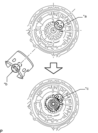
Text in Illustration *a Spline *b Protrusion *c Spline and Protrusion Install the No. 2 brake piston to the automatic transmission case sub-assembly.
Tech Tips
Make sure that the parking hole of the No. 2 brake piston is on the bottom side by engaging the 2 protrusions of the brake piston to the spline grooves of the transmission case.
-
Install the No. 2 brake piston return spring sub-assembly to the automatic transmission case sub-assembly.
-
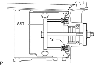
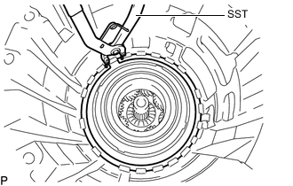
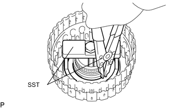
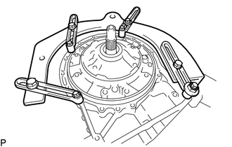
Text in Illustration *1 No. 2 Brake Piston Return Spring Sub-assembly *2 Snap Ring Set SST on the No. 2 brake piston return spring sub-assembly, tighten SST and compress the No. 2 brake piston return spring sub-assembly.
- SST
- 09380-50010 ( 09381-05010, 09381-05020, 09381-05030, 09381-05040, 09381-05050 )
-
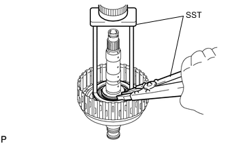
Using SST, install the snap ring.
- SST
- 09350-30020 ( 09350-07070 )
-
-
INSPECT PACK CLEARANCE OF NO. 2 BRAKE
-
INSTALL DIRECT CLUTCH PISTON
-
Coat a new O-ring with ATF, and install it to the direct clutch drum sub-assembly.
-
Coat a new O-ring with ATF, and install it to the direct clutch piston.
-
Text in Illustration *1 Direct Clutch Piston Install the direct clutch piston to the direct clutch drum sub-assembly.
-
Coat a new O-ring with ATF, and install it to the No. 2 clutch balancer.
-
Text in Illustration *1 No. 2 Clutch Balancer *2 Direct Clutch Return Spring Sub-assembly Install the direct clutch return spring sub-assembly and No. 2 clutch balancer to the direct clutch drum sub-assembly.
-
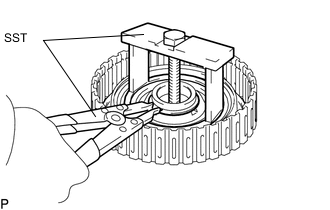
Place SST on the No. 2 clutch balancer and compress the direct clutch return spring sub-assembly with a press.
- SST
- 09387-00020
-
Using SST, install the snap ring.
- SST
- 09350-30020 ( 09350-07070 )
-
-
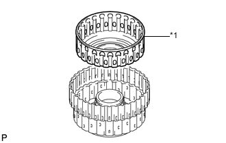
INSTALL NO. 2 CLUTCH DISC SET
-
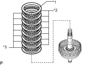
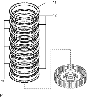
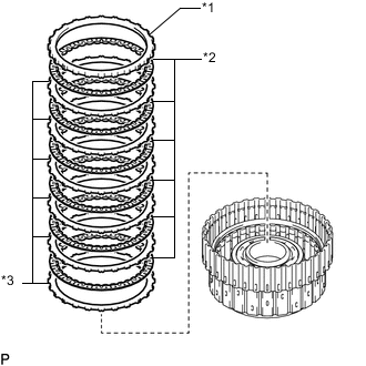
Text in Illustration *1 No. 2 Clutch Flange *2 No. 2 Clutch Disc *3 No. 2 Clutch Plate Install the 7 No. 2 clutch plates, 7 No. 2 clutch discs and the No. 2 clutch flange to the direct clutch drum sub-assembly.
Install in order *3 - *2 - *3 - *2 - *3 - *2 - *3 - *2 - *3 - *2 - *3 - *2 - *3 - *2 - *1 Note
Make sure that the No. 2 clutch discs, No. 2 clutch plates and the No. 2 clutch flange are installed in the correct order.
-
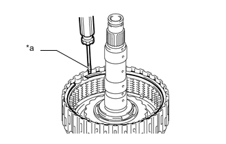
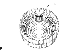
Text in Illustration *a Protective Tape Using a screwdriver, install the snap ring to the direct clutch drum sub-assembly.
Note
Be careful not to damage the direct clutch drum sub-assembly.
Tech Tips
Tape the screwdriver tip before use.
-
-
INSPECT PACK CLEARANCE OF NO. 2 CLUTCH
-
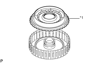
INSTALL DIRECT MULTIPLE DISC CLUTCH ASSEMBLY
-
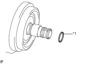
Text in Illustration *1 Oil Seal Ring Coat a new oil seal ring with ATF, and install them to the direct multiple disc clutch assembly.
Note
Do not expand the gap of the oil seal rings excessively.
-
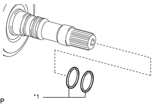
Text in Illustration *1 Oil Seal Ring Coat 2 new oil seal ring with ATF, and install them to the output shaft sub-assembly.
Note
Do not expand the gap of the oil seal rings excessively.
-
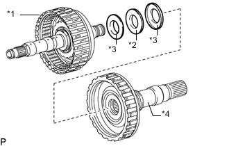
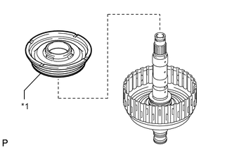
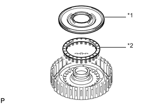
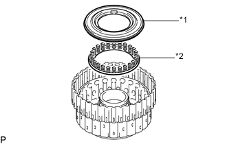
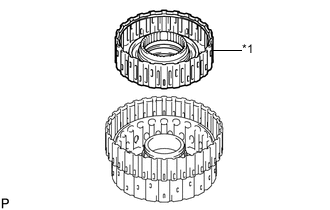
Text in Illustration *1 Direct Multiple Disc Clutch Assembly *2 Thrust Needle Roller Bearing (G) *3 Thrust Bearing Race (G) *4 Output Shaft Sub-assembly Install the thrust needle roller bearing and 2 thrust bearing races to the direct multiple disc clutch assembly.
Thrust Needle Roller Bearing and Thrust Bearing Race Diameter Item Inside Outside for Front Side:
Thrust bearing race (G)
26.2 mm (1.031 in.) 52.7 mm (2.075 in.) Thrust needle roller bearing (G) 29.3 mm (1.154 in.) 51.2 mm (2.016 in.) for Rear Side:
Thrust bearing race (G)
29.3 mm (1.154 in.) 54.0 mm (2.126 in.) Note
Use a small amount of MP grease to make the thrust needle roller bearing and thrust bearing race stay securely in place.
-
Install the direct multiple disc clutch assembly to the output shaft sub-assembly.
-
-
INSTALL REAR PLANETARY RING GEAR
-
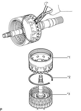
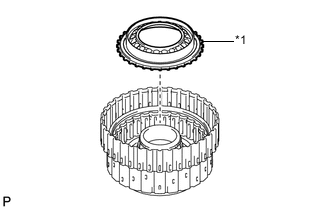
Text in Illustration *1 Rear Planetary Ring Gear *2 Snap Ring *3 Output Shaft Sub-assembly Install the snap ring to the groove of the output shaft sub-assembly.
-
Using needle-nose pliers, attach the snap ring to install the rear planetary ring gear to the output shaft sub-assembly.
-
-
INSTALL DIRECT MULTIPLE DISC CLUTCH ASSEMBLY WITH REAR PLANETARY RING GEAR AND OUTPUT SHAFT SUB-ASSEMBLY
-
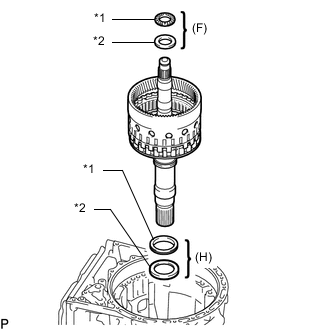
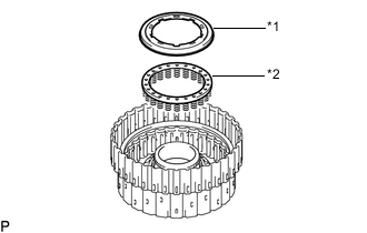
Text in Illustration *1 Thrust Needle Roller Bearing *2 Thrust Bearing Race Install the 2 thrust needle bearings, 2 thrust bearing races, direct multiple disc clutch assembly with rear planetary ring gear and output shaft sub-assembly to the automatic transmission case sub-assembly.
Thrust Needle Roller Bearing and Thrust Bearing Race Diameter Item Inside Outside Thrust bearing race (H) 62.0 mm (2.441 in.) 82.5 mm (3.248 in.) Thrust needle roller bearing (H) 58.9 mm (2.319 in.) 76.7 mm (3.020 in.) for Rear Side:
Thrust bearing race (F)
28.7 mm (1.130 in.) 53.5 mm (2.106 in.) Thrust needle roller bearing (F) 28.7 mm (1.130 in.) 53.8 mm (2.118 in.) Note
Use a small amount of MP grease to make the thrust needle roller bearing and thrust bearing race stay securely in place.
-
-
INSTALL REAR PLANETARY GEAR ASSEMBLY
-
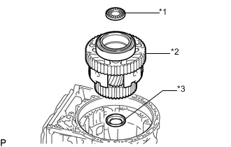
Text in Illustration *1 Thrust Needle Roller Bearing *2 Rear Planetary Gear Assembly *3 Thrust Bearing Race Install the thrust bearing race, rear planetary gear assembly and thrust needle roller bearing to the automatic transmission case sub-assembly.
Thrust Needle Roller Bearing and Thrust Bearing Race Diameter Item Inside Outside for Front Side
Thrust bearing race (F)
31.5 mm (1.240 in.) 57.3 mm (2.256 in.) Thrust needle roller bearing (E) 31.0 mm (1.221 in.) 53.7 mm (2.114 in.) Note
-
Before installing the rear planetary gear assembly, apply ATF to the sliding surfaces of the rear planetary gear assembly bush. After the installation, check that the rear planetary gear assembly rotates smoothly.
-
Use a small amount of MP grease to make the thrust needle roller bearing and thrust bearing race stay securely in place.
-
-
-
INSTALL REAR PLANETARY SUN GEAR SUB-ASSEMBLY
-
Text in Illustration *1 Rear Planetary Sun Gear Sub-assembly *2 Thrust Bearing Race (E) Install the thrust bearing race and rear planetary sun gear sub-assembly to the automatic transmission case sub-assembly.
Standard Thrust Bearing Race Diameter Item Inside Outside Thrust bearing race (E) 30.0 mm (1.181 in.) 49.9 mm (1.965 in.) Note
-
Before installing the rear planetary sun gear sub-assembly, apply ATF to the sliding surfaces of the rear planetary sun gear sub-assembly bush. After the installation, check that the rear planetary sun gear sub-assembly rotates smoothly.
-
Use a small amount of MP grease to make the thrust bearing race stay securely in place.
-
-
-
INSTALL NO. 2 BRAKE DISC SET
-
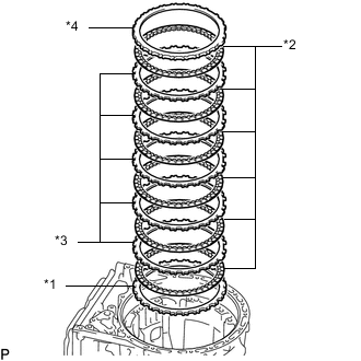
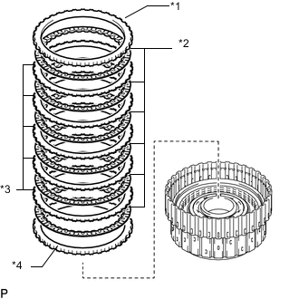
Text in Illustration *1 Brake Plate *2 No. 2 Brake Disc *3 No. 2 Brake Plate *4 No. 2 Brake Flange Install the No. 2 brake flange, 6 No. 2 brake discs, 5 No. 2 brake plates and brake plate to the automatic transmission case sub-assembly.
Install in order *4 - *2 - *3 - *2 - *3 - *2 - *3 - *2 - *3 - *2 - *3 - *2 - *1 Note
Make sure that the No. 2 brake discs, No. 2 brake plates, brake plate and No. 2 brake flange are installed in the correct order.
Tech Tips
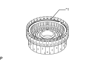
Assemble the automatic transmission case sub-assembly, No. 2 brake flange, No. 2 brake plate and brake plate by aligning their grooves as shown in the illustration.
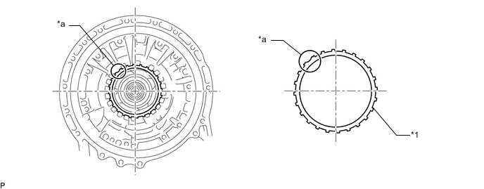
Text in Illustration *1 Brake Plate, No. 2 Brake Plate and No. 2 Brake Flange - - *a Groove - - -
Install the snap ring to the automatic transmission case sub-assembly.
-
-
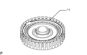
INSTALL NO. 1 ONE-WAY CLUTCH
-
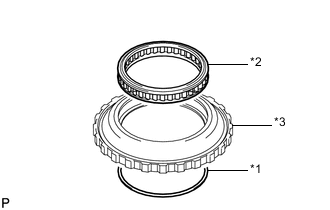
Text in Illustration *1 Snap Ring *2 No. 1 One-way Clutch *3 One-way Clutch Outer Race Install the No. 1 one-way clutch to the one-way clutch outer race with the snap ring.
Note
Make sure that the No. 1 one-way clutch is oriented correctly.
-
-
INSPECT NO. 1 ONE-WAY CLUTCH
-
INSTALL ONE-WAY CLUTCH OUTER RACE WITH NO. 1 ONE-WAY CLUTCH
-
Install the one-way clutch outer race with No. 1 one-way clutch to the automatic transmission case sub-assembly.
-
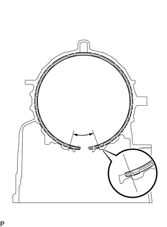
Using SST, install the snap ring to the automatic transmission case sub-assembly.
- SST
- 09350-30020 ( 09350-07060 )
Note
Install the snap ring so that its end gap will be within the range shown in the illustration.
-
-
INSTALL SUN GEAR INPUT DRUM SUB-ASSEMBLY
-
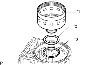
Text in Illustration *1 Sun Gear Input Drum Sub-assembly *2 Thrust Needle Roller Bearing (D) *3 Thrust Bearing Race (D) Install the thrust bearing race, thrust needle roller bearing and sun gear input drum sub-assembly to the automatic transmission case sub-assembly.
Thrust Needle Roller Bearing and Thrust Bearing Race Diameter Item Inside Outside Thrust bearing race (D) 71.9 mm (2.831 in.) 87.8 mm (3.457 in.) Thrust needle roller bearing (D) 71.2 mm (2.803 in.) 84.5 mm (3.327 in.) Note
-
Before installing the sun gear input drum sub-assembly, apply ATF to the sliding surfaces of the sun gear input drum sub-assembly bush. After the installation, check that the sun gear input drum sub-assembly rotates smoothly.
-
Use a small amount of MP grease to make the thrust needle roller bearing and thrust bearing race stay securely in place.
-
-
-
INSTALL FORWARD CLUTCH PISTON
-
Coat 2 new O-rings with ATF, and install them to the forward clutch piston.
-
Text in Illustration *1 Forward Clutch Piston Install the forward clutch piston to the forward clutch drum sub-assembly.
-
Coat a new O-ring with ATF, and install it to the No. 1 clutch balancer.
-
Text in Illustration *1 No. 1 Clutch Balancer *2 Forward Clutch Return Spring Sub-assembly Install the forward clutch return spring sub-assembly and No. 1 clutch balancer to the forward clutch drum sub-assembly.
-
Set SST on the No. 1 clutch balancer, tighten SST and compress the No. 1 clutch balancer.
- SST
- 09380-50010 ( 09381-05010, 09381-05020, 09381-05030, 09381-05040, 09381-05050 )
Note
Stop pressing when the balancer is lowered to the place 1 to 2 mm (0.039 to 0.078 in.) from the snap ring groove to prevent spring sheet deformation.
-
Using SST, install the snap ring.
- SST
- 09350-30020 ( 09350-07070 )
Note
-
Be sure that the end gap of the snap ring is not aligned with the spring retainer claw.
-
Do not expand the snap ring excessively.
-
-
INSTALL FORWARD MULTIPLE CLUTCH DISC SET
-
Text in Illustration *1 Forward Clutch Flange *2 Forward Multiple Clutch Disc *3 Forward Multiple Clutch Plate Install the 7 forward multiple clutch plates, 7 forward multiple clutch discs and forward clutch flange to the forward clutch drum sub-assembly.
Install in order *3 - *2 - *3 - *2 - *3 - *2 - *3 - *2 - *3 - *2 - *3 - *2 - *3 - *2 - *1 Note
Make sure that the forward multiple clutch discs, forward multiple clutch plates and the forward clutch flange are installed in the correct order.
-
Text in Illustration *1 Snap Ring Install the snap ring to the forward clutch drum sub-assembly.
-
-
INSPECT PACK CLEARANCE OF FORWARD MULTIPLE CLUTCH
-
INSTALL FRONT PLANETARY RING GEAR
-
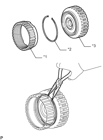
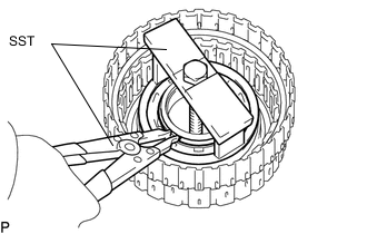
Text in Illustration *1 Front Planetary Ring Gear *2 Snap Ring *3 Forward Multiple Disc Clutch Assembly Using needle-nose pliers, install the snap ring to the groove of forward multiple disc clutch assembly.
-
Using needle-nose pliers, contract the snap ring and install the front planetary ring gear to the forward multiple disc clutch assembly.
Note
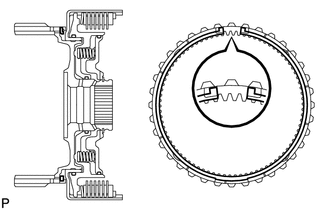
Confirm that the snap ring is correctly located in the groove of the forward multiple disc clutch assembly as shown in the illustration.
-
-
INSTALL FORWARD MULTIPLE DISC CLUTCH HUB
-
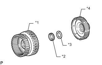
Text in Illustration *1 Forward Multiple Disc Clutch Assembly with Front Planetary Ring Gear *2 Thrust Needle Roller Bearing (B) *3 Thrust Bearing Race (B) *4 Forward Multiple Disc Clutch Hub Install the thrust needle roller bearing, thrust bearing race and forward multiple disc clutch assembly with front planetary ring gear to the forward multiple disc clutch hub.
Thrust Needle Roller Bearing and Thrust Bearing Race Diameter Item Inside Outside Thrust needle roller bearing (B) 34.5 mm (1.358 in.) 49.9 mm (1.965 in.) Thrust bearing race (B) 36.6 mm (1.441 in.) 51.9 mm (2.043 in.) Note
Use a small amount of MP grease to make the thrust needle roller bearing and thrust bearing race stay securely in place.
-
-
INSTALL FORWARD MULTIPLE DISC CLUTCH ASSEMBLY WITH FRONT PLANETARY RING GEAR AND FORWARD MULTIPLE DISC CLUTCH HUB
-
Text in Illustration *1 Forward Multiple Disc Clutch Assembly with Front Planetary Ring Gear *2 Thrust Bearing Race (C) *3 Thrust Needle Roller Bearing (C) Install the thrust bearing race, thrust needle roller bearing and forward multiple disc clutch assembly with front planetary ring gear and forward multiple disc clutch hub to the automatic transmission case sub-assembly.
Thrust Needle Roller Bearing and Thrust Bearing Race Diameter Item Inside Outside Thrust needle race (C) 47.0 mm (1.850 in.) 61.9 mm (2.437 in.) Thrust bearing roller bearing (C) 46.5 mm (1.831 in.) 60.1 mm (2.366 in.) Note
-
Before installing the forward multiple disc clutch assembly, apply ATF to the sliding surfaces of the forward multiple disc clutch assembly bush. After the installation, check that the forward multiple disc clutch assembly rotates smoothly.
-
Use a small amount of MP grease to make the thrust needle roller bearing and thrust needle roller bearing race stay securely in place.
-
-
-
INSTALL REVERSE CLUTCH PISTON SUB-ASSEMBLY
-
Coat a new O-ring with ATF, and install it to the reverse clutch drum sub-assembly.
-
Text in Illustration *1 Reverse Clutch Piston Sub-assembly Install the reverse clutch piston sub-assembly to the reverse clutch drum sub-assembly.
-
Coat a new O-ring with ATF, and install it to the No. 3 clutch balancer.
-
Text in Illustration *1 No. 3 Clutch Balancer *2 Reverse Clutch Return Spring Sub-assembly (Front) Install the reverse clutch return spring sub-assembly (front) and No. 3 clutch balancer to the reverse clutch drum sub-assembly.
-
Set SST on the No. 3 clutch balancer, tighten SST and compress the No. 3 clutch balancer.
- SST
- 09380-50010 ( 09381-05010, 09381-05020, 09381-05030, 09381-05040, 09381-05050 )
Note
Stop pressing when the balancer is lowered to the place 1.0 to 2.0 mm (0.0394 to 0.0787 in.) from the snap ring groove to prevent spring sheet deformation.
-
Using SST, install the snap ring.
- SST
- 09350-30020 ( 09350-07070 )
Note
-
Be sure that the end gap of the snap ring is not aligned with the spring retainer claw.
-
Do not expand the snap ring excessively.
-
-
INSTALL OVERDRIVE DIRECT CLUTCH DRUM SUB-ASSEMBLY
-
Coat 3 new O-rings with ATF, and install them to the overdrive direct clutch drum sub-assembly.
-
Text in Illustration *1 Overdrive Direct Clutch Drum Sub-assembly Install the overdrive direct clutch drum sub-assembly to the reverse clutch drum sub-assembly.
-
-
INSTALL NO. 4 CLUTCH PISTON
-
Coat a new O-ring with ATF, and install it to the No. 4 clutch piston.
-
Text in Illustration *1 No. 4 Clutch Piston Install the No. 4 clutch piston to the overdrive direct clutch drum sub-assembly.
-
Text in Illustration *1 Reverse Clutch Balancer *2 Reverse Clutch Return Spring Sub-assembly (Rear) Install the reverse clutch return spring sub-assembly (rear) and reverse clutch balancer to the overdrive direct clutch drum sub-assembly.
-
Set SST on the reverse clutch balancer, tighten SST and compress the reverse clutch balancer.
- SST
- 09380-50010 ( 09381-05010, 09381-05020, 09381-05030, 09381-05040, 09381-05050 )
Note
Stop pressing when the balancer is lowered to the place 1.0 to 2.0 mm (0.0394 to 0.0787 in.) from the snap ring groove to prevent spring sheet deformation.
-
Using SST, install the snap ring.
- SST
- 09350-30020 ( 09350-07070 )
Note
-
Be sure that the end gap of the snap ring is not aligned with the spring retainer claw.
-
Do not expand the snap ring excessively.
-
-
INSTALL OVERDRIVE DIRECT CLUTCH DISC
-
Text in Illustration *1 Overdrive Clutch Flange *2 Overdrive Direct Clutch Disc *3 Overdrive Direct Clutch Plate Install the 6 overdrive direct clutch plates, 6 overdrive direct clutch discs and overdrive clutch flange to the overdrive direct clutch drum sub-assembly.
Install in order *3 - *2 - *3 - *2 - *3 - *2 - *3 - *2 - *3 - *2 - *3 - *2 - *1 Note
Make sure that the overdrive direct clutch discs, overdrive direct clutch plates and the overdrive clutch flange are installed in the correct order.
-
Text in Illustration *1 Snap Ring Install the snap ring to the overdrive direct clutch drum sub-assembly.
-
-
INSPECT PACK CLEARANCE OF OVERDRIVE DIRECT CLUTCH
-
INSTALL NO. 3 CLUTCH DISC SET
-
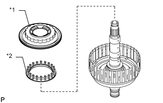
Text in Illustration *1 No. 3 Clutch Flange *2 No. 3 Clutch Discs *3 No. 3 Clutch Plate (A) *4 No. 3 Clutch Plate (B) Install the 6 No. 3 clutch plates, 6 No. 3 clutch discs and No. 3 clutch flange to the reverse clutch drum sub-assembly.
Install in order *4 - *2 - *3 - *2 - *3 - *2 - *3 - *2 - *3 - *2 - *3 - *2 - *1 No. 3 Clutch Plate Thickness Item Thickness No. 3 Clutch Plate (A) 1.8 mm (0.0709 in.) No. 3 Clutch Plate (B) 3.5 mm (0.138 in.) Note
Make sure that the No. 3 clutch discs, No. 3 clutch plates and the No. 3 clutch flange are installed in the correct order.
-
Text in Illustration *1 Snap Ring Install the snap ring to the reverse clutch drum sub-assembly.
-
-
INSPECT PACK CLEARANCE OF NO. 3 CLUTCH
-
INSTALL FRONT PLANETARY GEAR ASSEMBLY
-
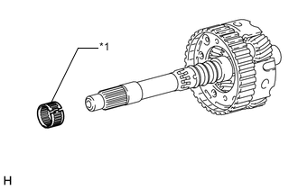
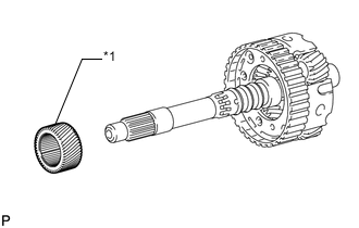
Text in Illustration *1 Front Planetary Gear Radial Needle Roller Bearing Install the front planetary gear radial needle roller bearing to the front planetary gear assembly.
Note
Do not expand the front planetary gear radial needle roller bearing excessively.
-
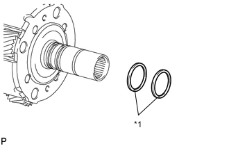
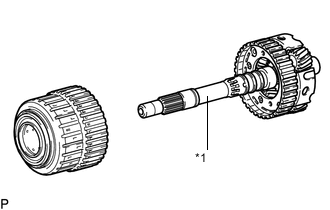
Text in Illustration *1 Oil Seal Ring Coat 2 new oil seal rings with ATF, and install them to the front planetary gear assembly.
Note
Do not expand the oil seal ring ends excessively.
-
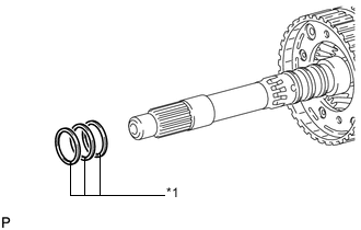
Text in Illustration *1 Oil Seal Ring Coat 3 new oil seal rings with ATF, and install them to the front planetary gear assembly.
Note
Do not expand the oil seal ring ends excessively.
-
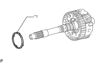
Text in Illustration *1 Planetary Carrier Thrust Washer Install the planetary carrier thrust washer to the front planetary gear assembly.
Note
Use a small amount of MP grease to make the planetary carrier thrust washer stay securely in place.
-
Text in Illustration *1 Front Planetary Sun Gear Install the front planetary sun gear to the front planetary gear assembly.
-
Text in Illustration *1 Front Planetary Gear Assembly Assemble the front planetary gear assembly together with the front planetary sun gear to the overdrive and reverse multiple disc clutch assembly.
-
-
INSPECT PACK CLEARANCE OF NO. 1 BRAKE
-
INSTALL OVERDRIVE AND REVERSE MULTIPLE DISC CLUTCH ASSEMBLY AND FRONT PLANETARY GEAR ASSEMBLY
-
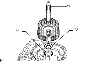
Text in Illustration *1 Overdrive and Reverse Multiple Disc Clutch Assembly and Front Planetary Gear Assembly *2 Thrust Needle Roller Bearing (A) *3 Thrust Bearing Race (A) Install the thrust bearing race, thrust needle roller bearing, and overdrive and reverse multiple disc clutch assembly and front planetary gear assembly to the automatic transmission case sub-assembly.
Thrust Needle Roller Bearing and Thrust Bearing Race Diameter Item Inside Outside Thrust needle roller bearing (A) 36.2 mm (1.425 in.) 58.2 mm (2.291 in.) Thrust bearing race (A) 44.0 mm (1.732 in.) 62.0 mm (2.441 in.) Note
-
Before installing the reverse clutch drum sub-assembly, apply ATF to the sliding surfaces of the reverse clutch drum sub-assembly. After the installation, check that the overdrive direct clutch drum sub-assembly rotates smoothly.
-
Use a small amount of MP grease to make the thrust bearing and thrust bearing race stay securely in place.
-
-
Install the snap ring to the automatic transmission case sub-assembly.
-
-
INSTALL NO. 1 BRAKE DISC SET
-
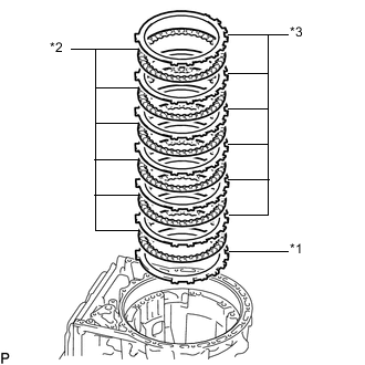
Text in Illustration *1 No. 1 Brake Flange *2 No. 1 Brake Disc *3 No. 1 Brake Plate Install the selected No. 1 brake flange, 6 No. 1 brake discs and 6 No. 1 brake plates to the automatic transmission case sub-assembly.
Install in order *1 - *2 - *3 - *2 - *3 - *2 - *3 - *2 - *3 - *2 - *3 - *2 - *3 Note
Make sure that the No. 1 brake discs, No. 1 brake plates and the No. 1 brake flange are installed in the correct order.
-
-
INSTALL OVERDRIVE BRAKE PLATE STOPPER SPRING
-
Install the overdrive brake plate stopper spring to the automatic transmission case sub-assembly as shown in the illustration.
Note
Install the overdrive brake plate stopper spring so that the wider side is facing inwards.
-
-
INSTALL OIL PUMP ASSEMBLY
-
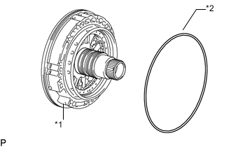
Text in Illustration *1 Oil Pump Assembly *2 Oil Pump O-ring Coat a new oil pump O-ring with ATF, and install it to the oil pump assembly.
-
Clean and degrease the threads of the 11 bolts and the contact surfaces of the automatic transmission case sub-assembly and the oil pump assembly with non-residue solvent.
Note
During installation, do not allow oil to contact the bolts or the surface of the oil pump assembly body.
-
Place the oil pump assembly through the input shaft, and align the bolt holes of the oil pump assembly with the automatic transmission case sub-assembly.
-
Hold the input shaft, and lightly press the oil pump assembly to slide the oil seal rings into the front planetary gear assembly.
Note
Be careful not to damage the O-ring and oil seal rings.
-
Install the 11 bolts.
- Torque:
- 25 N*m { 250 kgf*cm, 18 ft.*lbf }
-
-
INSPECT INDIVIDUAL PISTON OPERATION
-
INSTALL MANUAL DETENT SPRING SUB-ASSEMBLY
-
Text in Illustration *1 Manual Detent Spring Sub-assembly *2 Manual Detent Spring Cover Install the manual detent spring sub-assembly and manual detent spring cover with the bolt.
- Torque:
- 10 N*m { 102 kgf*cm, 7 ft.*lbf }
-
-
INSTALL MANUAL VALVE LEVER SHAFT OIL SEAL
-
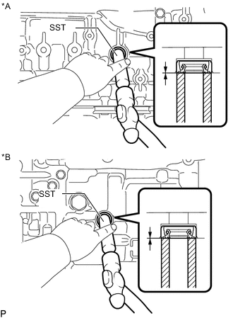
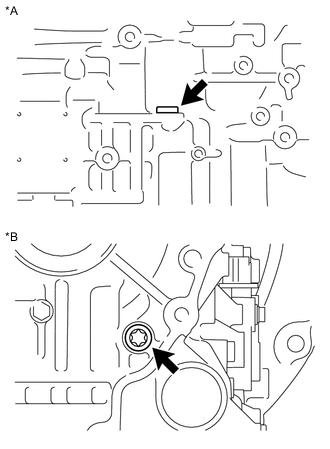
Text in Illustration *A for RH Side *B for LH Side Using SST and a hammer, tap in 2 new manual valve lever shaft oil seals.
- SST
- 09350-30020 ( 09350-07110 )
Standard depth -0.2 to 0.4 mm (-0.00788 to 0.0157 in.) -
Coat the lip of the 2 manual valve lever shaft oil seals with MP grease.
-
-
INSTALL PARKING LOCK PAWL SHAFT
-
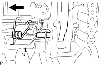
Text in Illustration *1 Parking Lock Pawl *2 Parking Lock Pawl Shaft *3 Spring *4 E-ring Install the E-ring to the parking lock pawl shaft.
-
Install the parking lock pawl, parking lock pawl shaft and spring.
-
-
INSTALL PARKING LOCK ROD SUB-ASSEMBLY
-
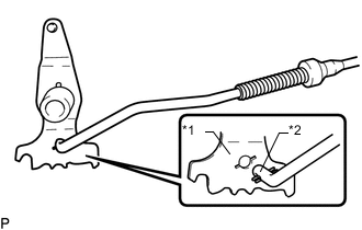
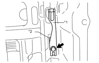
Text in Illustration *1 Manual Valve Lever Sub-assembly *2 Parking Lock Rod Sub-assembly Connect the parking lock rod sub-assembly to the manual valve lever sub-assembly.
-
-
INSTALL MANUAL VALVE LEVER SUB-ASSEMBLY
-
Text in Illustration *1 Spacer Install a new spacer to the manual valve lever sub-assembly.
-
Install the manual valve lever shaft to the manual valve lever sub-assembly and automatic transmission case sub-assembly.
-
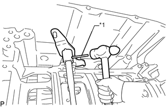
Text in Illustration *1 Spring Pin Using a hammer, install a new spring pin.
-
Turn the spacer and manual valve lever shaft to align the smaller hole on the spacer with the indent on the manual valve lever sub-assembly.
-
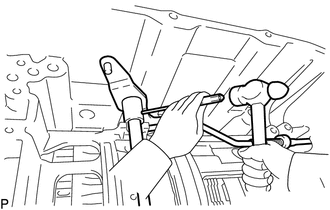
Using a 3 mm pin punch and a hammer, stake the spacer.
-
Check that the spacer does not turn.
-
-
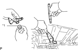
INSTALL PARKING LOCK PAWL BRACKET
-
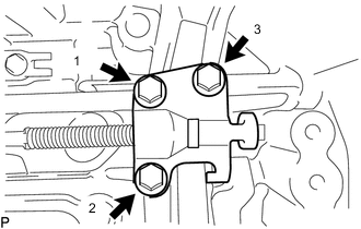
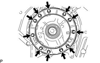
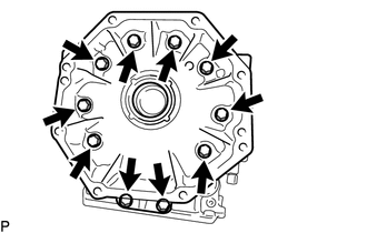
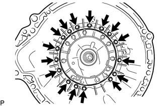
Install the parking lock pawl bracket to the automatic transmission case sub-assembly with the 3 bolts, in several steps in the order shown in the illustration.
- Torque:
- 18 N*m { 184 kgf*cm, 13 ft.*lbf }
-
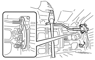
Move the manual valve lever sub-assembly to the P position, and check the output shaft sub-assembly is locked by the parking lock pawl.
-
-
INSTALL TRANSMISSION REVOLUTION SENSOR (SP2)
-
INSTALL TRANSMISSION WIRE
-
INSTALL TRANSMISSION VALVE BODY ASSEMBLY
-
INSTALL VALVE BODY OIL STRAINER ASSEMBLY
-
INSTALL AUTOMATIC TRANSMISSION OIL PAN SUB-ASSEMBLY
-
INSTALL AUTOMATIC TRANSMISSION CASE PLUG
-
Text in Illustration *A for LH Side *B for Rear Side for T55H "TORX" Type:
-
Install the 2 new O-rings to the 2 automatic transmission case plugs.
-
Using a T55H "TORX" socket wrench, install the 2 automatic transmission case plugs to the automatic transmission case sub-assembly.
- Torque:
- 40 N*m { 403 kgf*cm, 30 ft.*lbf }
-
-
for 17 mm Hexagon Type:
-
Install a new O-ring to the automatic transmission case plug.
-
Install the automatic transmission case plug to the automatic transmission case sub-assembly.
- Torque:
- 80 N*m { 816 kgf*cm, 59 ft.*lbf }
-
-
-
INSTALL REFILL PLUG
-
Install a new O-ring to the refill plug.
-
Install the refill plug.
- Torque:
- 39 N*m { 400 kgf*cm, 29 ft.*lbf }
-
-
INSTALL OIL COOLER TUBE UNION
-
Install the 2 new O-rings to the 2 oil cooler tube unions.
-
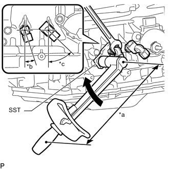
Text in Illustration *a Torque Wrench Fulcrum Length *b 18 to 22° *c 43 to 47° Using SST, install the 2 oil cooler tube unions to the automatic transmission case sub-assembly.
- SST
- 09268-78010
- Torque:
- Specified tightening torque
- 29 N*m { 300 kgf*cm, 22 ft.*lbf }
Tech Tips
-
Calculate the torque wrench reading when changing the fulcrum length of the torque wrench Click here.
-
When using SST (fulcrum length of 34.5 mm (1.3583 in.)) + torque wrench (fulcrum length of 180 mm (7.0866 in.)): 25 N*m (252 kgf*cm, 18 ft.*lbf)
-
-
INSTALL PARK/NEUTRAL POSITION SWITCH ASSEMBLY
-
INSTALL REAR TRANSFER ADAPTER
-
Coat a new O-ring with ATF and install it to the rear transfer adapter.
-
Install the rear transfer adapter with the 10 bolts.
- Torque:
- 34 N*m { 345 kgf*cm, 25 ft.*lbf }
-
-
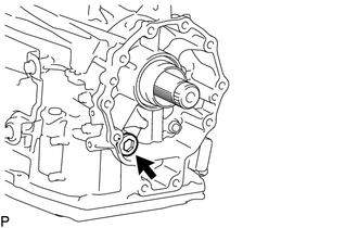
INSTALL TRANSFER CASE ADAPTER REAR OIL SEAL
-
Coat the lip of a new transfer case adapter rear oil seal with MP grease.
-
Using SST and a hammer, tap in the transfer case adapter rear oil seal.
- SST
- 09223-50010
- 09710-30031 ( 09710-03171 )
Standard depth 0 to 1 mm (0 to 0.0393 in.)
-
-
INSTALL AUTOMATIC TRANSMISSION HOUSING
-
Remove the automatic transmission assembly from the overhaul attachment.
-
Install the automatic transmission housing to the automatic transmission case sub-assembly with the 16 bolts.
- Torque:
- 25 N*m { 250 kgf*cm, 18 ft.*lbf }
-
-
INSTALL TRANSMISSION BREATHER HOSE SUB-ASSEMBLY
-
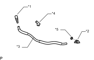
Text in Illustration *1 No. 2 Breather Plug *2 No. 1 Breather Plug *3 Breather Plug Hose *4 Clamp *5 Breather Plug O-ring Coat a new breather plug O-ring with ATF, and install it to the No. 1 breather plug.
Note
Ensure that the breather plug O-ring is not twisted.
-
Install the No. 1 breather plug and No. 2 breather plug to the breather plug hose.
-
Install the clamp to the breather plug hose.
-
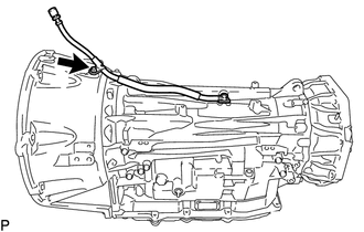
Install the transmission breather hose sub-assembly to the automatic transmission case sub-assembly with the bolt.
- Torque:
- 5.4 N*m { 55 kgf*cm, 48 in.*lbf }
-