AUTOMATIC TRANSMISSION UNIT INSPECTION

PROCEDURE
-
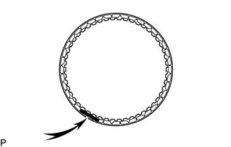
INSPECT NO. 1 BRAKE DISC
-
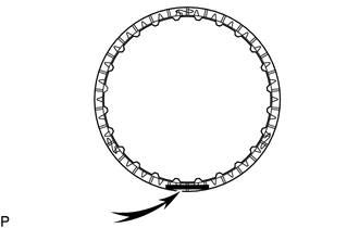
Check whether the sliding surfaces of the No. 1 brake discs, No. 1 brake plates and the No. 1 brake flange are worn or burnt.
Note
-
If the linings of the No. 1 brake discs are peeled off or discolored, or if any part of the printed numbers is damaged, replace all the No. 1 brake discs.
-
Before assembling new No. 1 brake discs, soak them in ATF for at least 2 hours.
If necessary, replace them.
-
-
-
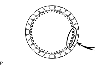
INSPECT FRONT PLANETARY GEAR ASSEMBLY
-
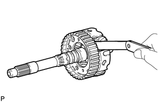
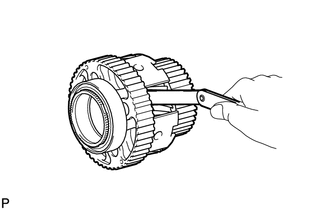
Using a feeler gauge, measure the clearance between the front planetary gear assembly and each pinion gear.
Standard Clearance 0.2 to 0.6 mm (0.00788 to 0.0236 in.) If the clearance is not as specified, replace the front planetary gear assembly.
-
-
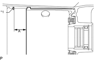
INSPECT PACK CLEARANCE OF NO. 1 BRAKE
-
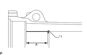
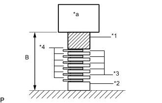
Text in Illustration *1 Snap Ring Using a vernier caliper, measure dimension A (from the step of the oil pump assembly installation surface of the automatic transmission case sub-assembly to the step of the No. 1 brake flange installation surface) in the illustration, and calculate the average.
Tech Tips
Dimension A = 46.18 to 46.54 mm (1.8182 to 1.8322 in.)
-
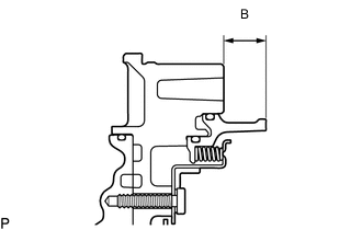
Using a vernier caliper, measure dimension B (from the flange face of the oil pump assembly to the tip of the No. 1 brake piston) in the illustration, and calculate the average.
Tech Tips
Dimension B = 19.23 to 19.57 mm (0.7571 to 0.7704 in.)
-
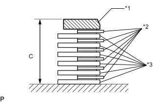
Text in Illustration *1 No. 1 Brake Flange *2 No. 1 Brake Disc *3 No. 1 Brake Plate Using a vernier caliper, assemble the 6 No. 1 brake plates, 6 No. 1 brake discs and No. 1 brake flange, measure dimension C in the illustration and calculate the average.
Tech Tips
-
Dimension C = 25.15 to 26.45 mm (0.9902 to 1.0413 in.)
-
Pack clearance = Dimension A - Dimension B - Dimension C
Standard Clearance 0.90 to 1.10 mm (0.0355 to 0.0433 in.) -
-
If the pack clearance is outside the standard range, select and install a No. 1 brake flange that brings the pack clearance within the standard range.
Tech Tips
There are 7 types of No. 1 brake flanges that can be used to adjust the pack clearance. Select the one with the most appropriate thickness.
No. 1 Brake Flange Thickness Part No. Mark Thickness 35676-60190 0 4.45 to 4.55 mm (0.1752 to 0.1791 in.) 35676-60200 1 4.55 to 4.65 mm (0.1792 to 0.1830 in.) 35676-60210 2 4.65 to 4.75 mm (0.1831 to 0.1870 in.) 35676-60220 3 4.75 to 4.85 mm (0.1871 to 0.1909 in.) 35676-60230 4 4.85 to 4.95 mm (0.1910 to 0.1948 in.) 35676-60240 5 4.95 to 5.05 mm (0.1949 to 0.1988 in.) 35676-60250 6 5.05 to 5.15 mm (0.1989 to 0.2027 in.)
-
-
INSPECT NO. 3 CLUTCH DISC
-

Check whether the sliding surfaces of the No. 3 clutch discs, No. 3 clutch plates and the No. 3 clutch flange are worn or burnt.
Note
-
If the linings of the No. 3 clutch discs are peeled off or discolored, or if any part of the printed numbers is damaged, replace all the No. 3 clutch discs.
-
Before assembling new No. 3 clutch discs, soak them in ATF for at least 2 hours.
If necessary, replace them.
-
-
-
INSPECT PACK CLEARANCE OF NO. 3 CLUTCH
-
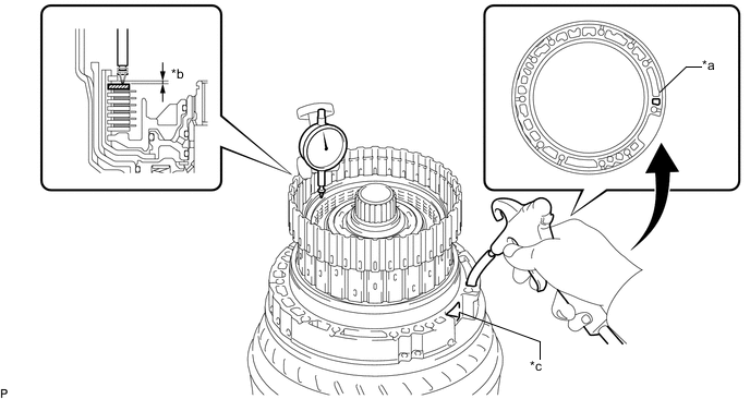
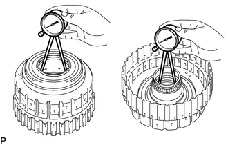
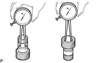
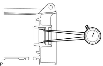
Using a dial indicator, measure the moving distance (distance A) of the No. 3 clutch flange at both ends across the diameter while blowing compressed air (196 kPa, 2.0 kgf/cm2, 28 psi) from the oil hole as shown in the illustration, and calculate the average.
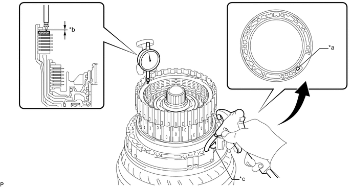
Text in Illustration *a Oil Hole *b Distance A *c Speed Sensor Hole - - Standard Clearance 0.90 to 1.10 mm (0.0355 to 0.0433 in.) -
If the pack clearance is outside the standard range, select and install a No. 3 clutch flange that brings the pack clearance within the standard range.
Tech Tips
There are 11 types of No. 3 clutch flanges that can be used to adjust the pack clearance. Select the one with the most appropriate thickness.
No. 3 Clutch Flange Thickness Part No. Thickness 34649-60250 3.75 to 3.85 mm (0.1477 to 0.1515 in.) 34649-60260 3.85 to 3.95 mm (0.1516 to 0.1555 in.) 34649-60270 3.95 to 4.05 mm (0.1556 to 0.1594 in.) 34649-60280 4.05 to 4.15 mm (0.1595 to 0.1633 in.) 34649-60290 4.15 to 4.25 mm (0.1634 to 0.1673 in.) 34649-60300 4.25 to 4.35 mm (0.1674 to 0.1712 in.) 34649-60310 4.35 to 4.45 mm (0.1713 to 0.1751 in.) 34649-60320 4.45 to 4.55 mm (0.1752 to 0.1791 in.) 34649-60330 4.55 to 4.65 mm (0.1792 to 0.1830 in.) 34649-60340 4.65 to 4.75 mm (0.1831 to 0.1870 in.) 34649-60350 4.75 to 4.85 mm (0.1871 to 0.1909 in.)
-
-
INSPECT OVERDRIVE DIRECT CLUTCH DISC
-
Check whether the sliding surfaces of the overdrive direct clutch discs, overdrive direct clutch plates and the overdrive clutch flange are worn or burnt.
Note
-
If the linings of the overdrive direct clutch discs are peeled off or discolored, or if any part of the printed numbers is damaged, replace all the overdrive direct clutch discs.
-
Before assembling new overdrive direct clutch discs, soak them in ATF for at least 2 hours.
If necessary, replace them.
-
-
-
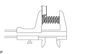
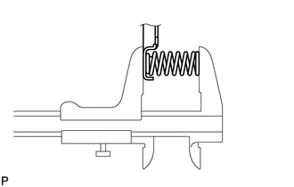
INSPECT REVERSE CLUTCH RETURN SPRING SUB-ASSEMBLY (REAR)
-
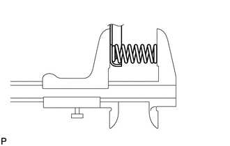
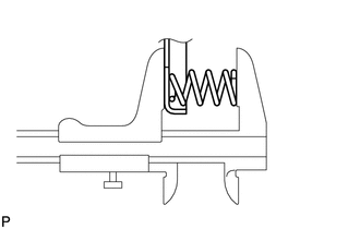
Using a vernier caliper, measure the free length of the spring together with the spring seat.
Standard Free Length 22.21 mm (0.874 in.) If the free length is shorter than the standard free length, replace the reverse clutch return spring sub-assembly (rear).
-
-
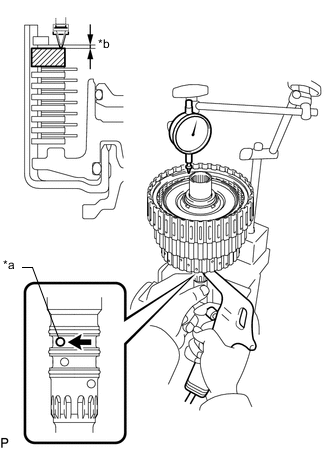
INSPECT PACK CLEARANCE OF OVERDRIVE DIRECT CLUTCH
-
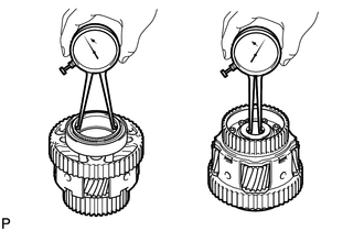
Using a dial indicator, measure the moving distance (distance A) of the reverse clutch flange at both ends across the diameter while blowing compressed air (300 kPa, 3.1 kgf/cm2, 44 psi) from the oil hole as shown in the illustration, and calculate the average.
Text in Illustration *a Oil Hole *b Distance A *c Speed Sensor Hole - - Standard Clearance 1.19 to 1.39 mm (0.0469 to 0.0547 in.) -
If the pack clearance is outside the standard range, select and install a overdrive clutch flange that brings the pack clearance within the standard range.
Tech Tips
There are 11 types of overdrive clutch flanges that can be used to adjust the pack clearance. Select the one with the most appropriate thickness.
Overdrive Clutch Flange Thickness Part No. Thickness 34615-60010 2.85 to 2.95 mm (0.1123 to 0.1161 in.) 34615-60020 2.95 to 3.05 mm (0.1162 to 0.1200 in.) 34615-60030 3.05 to 3.15 mm (0.1201 to 0.1240 in.) 34615-60040 3.15 to 3.25 mm (0.1241 to 0.1279 in.) 34615-60050 3.25 to 3.35 mm (0.1280 to 0.1318 in.) 34615-60060 3.35 to 3.45 mm (0.1319 to 0.1358 in.) 34615-60070 3.45 to 3.55 mm (0.1359 to 0.1397 in.) 34615-60080 3.55 to 3.65 mm (0.1398 to 0.1437 in.) 34615-60090 3.65 to 3.75 mm (0.1438 to 0.1476 in.) 34615-60100 3.75 to 3.85 mm (0.1477 to 0.1515 in.) 34615-60110 3.85 to 3.95 mm (0.1516 to 0.1555 in.)
-
-
INSPECT REVERSE CLUTCH RETURN SPRING SUB-ASSEMBLY (FRONT)
-
Using a vernier caliper, measure the free length of the spring together with the spring seat.
Standard Free Length 21.59 mm (0.850 in.) If the free length is shorter than the standard free length, replace the reverse clutch return spring sub-assembly (front).
-
-
INSPECT REVERSE CLUTCH DRUM SUB-ASSEMBLY
-
Using a caliper gauge, measure the inside diameter of the reverse clutch drum sub-assembly bush.
Standard Inside Diameter (Front Side) 67.40 to 67.44 mm (2.6536 to 2.6551 in.) Standard Inside Diameter (Rear Side) 55.62 to 55.64 mm (2.1898 to 2.1905 in.) If the inside diameter is not as specified, replace the reverse clutch drum sub-assembly.
-
-
INSPECT FORWARD MULTIPLE CLUTCH DISC
-
Check whether the sliding surfaces of the forward multiple clutch discs, forward multiple clutch plates and forward clutch flange are worn or burnt.
Note
-
If the linings of the forward multiple clutch discs are peeled off or discolored, replace all the forward multiple clutch discs.
-
Before assembling new forward multiple clutch discs, soak them in ATF for at least 2 hours.
If necessary, replace them.
-
-
-
INSPECT FORWARD CLUTCH RETURN SPRING SUB-ASSEMBLY
-
Using a vernier caliper, measure the free length of the spring together with the spring seat.
Standard Free Length 20.82 mm (0.820 in.) If the free length is shorter than the standard free length, replace the forward clutch return spring sub-assembly.
-
-
INSPECT PACK CLEARANCE OF FORWARD MULTIPLE CLUTCH
-
Temporarily assemble the front planetary gear assembly to the forward clutch drum sub-assembly.
-
Text in Illustration *a Oil Hole *b Distance A Using a dial indicator, measure the moving distance (distance A) of the forward clutch flange at both ends across the diameter while blowing compressed air (196 kPa, 2.0 kgf/cm2, 28 psi) from the oil hole as shown in the illustration, and calculate the average.
Standard Clearance 1.05 to 1.25 mm (0.0414 to 0.0492 in.) -
If the pack clearance is outside the standard range, select and install a forward clutch flange that brings the pack clearance within the standard range.
Tech Tips
There are 9 types of forward clutch flanges that can be used to adjust the pack clearance. Select the one with the most appropriate thickness.
Forward Clutch Flange Thickness Part No. Mark Thickness 35635-50090 0 4.35 to 4.45 mm (0.1713 to 0.1751 in.) 35635-50100 1 4.45 to 4.55 mm (0.1752 to 0.1791 in.) 35635-50110 2 4.55 to 4.65 mm (0.1792 to 0.1830 in.) 35635-50120 3 4.65 to 4.75 mm (0.1831 to 0.1870 in.) 35635-50130 4 4.75 to 4.85 mm (0.1871 to 0.1909 in.) 35635-50140 5 4.85 to 4.95 mm (0.1910 to 0.1948 in.) 35635-50150 6 4.95 to 5.05 mm (0.1949 to 0.1988 in.) 35635-50160 7 5.05 to 5.15 mm (0.1989 to 0.2027 in.) 35635-50170 8 5.15 to 5.25 mm (0.2028 to 0.2066 in.)
-
-
INSPECT FORWARD CLUTCH DRUM SUB-ASSEMBLY
-
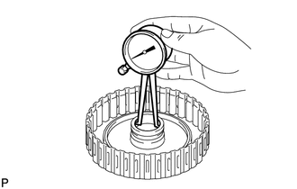
Using a caliper gauge, measure the inside diameter of the forward clutch drum bush.
Standard Inside Diameter 33.200 to 33.225 mm (1.3071 to 1.3080 in.) If the inside diameter is not as specified, replace the forward clutch drum sub-assembly.
-
-
INSPECT SUN GEAR INPUT DRUM SUB-ASSEMBLY
-
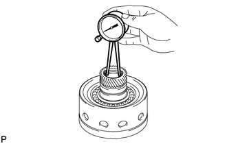
Using a caliper gauge, measure the inside diameter of the sun gear input drum bush.
Standard Inside Diameter 45.066 to 45.091 mm (1.7743 to 1.7752 in.) If the inside diameter is not as specified, replace the sun gear input drum sub-assembly.
-
-
INSPECT REAR PLANETARY SUN GEAR SUB-ASSEMBLY
-
Using a caliper gauge, measure the inside diameter of the rear planetary sun gear bush.
Standard Inside Diameter 28.760 to 28.781 mm (1.1323 to 1.1331 in.) If the inside diameter is not as specified, replace the rear planetary sun gear sub-assembly.
-
-
INSPECT REAR PLANETARY GEAR ASSEMBLY
-
Using a feeler gauge, measure the rear planetary gear pinion long and short thrust clearance.
Standard Clearance 0.2 to 0.6 mm (0.00788 to 0.0236 in.) If the clearance is not as specified, replace the rear planetary gear assembly.
-
Using a caliper gauge, measure the inside diameter of the rear planetary gear bush.
Standard Inside Diameter (Front Side) 70.60 to 70.63 mm (2.7796 to 2.7807 in.) Standard Inside Diameter (Rear Side) 28.700 to 28.721 mm (1.1300 to 1.1307 in.) If the inside diameter is not as specified, replace the rear planetary gear assembly.
-
-
INSPECT NO. 1 ONE-WAY CLUTCH
-
Install the No. 1 one-way clutch to the rear planetary gear assembly.
-
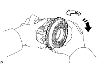
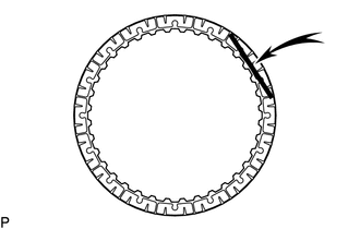
Hold the rear planetary gear assembly and turn the No. 1 one-way clutch.
Text in Illustration 
Lock 
Free -
Check that the No. 1 one-way clutch turns freely counterclockwise and locks clockwise.
If the No. 1 one-way clutch does not operate normally, replace it.
-
-
INSPECT NO. 2 BRAKE DISC
-
Check whether the sliding surfaces of the No. 2 brake discs, brake plate, No. 2 brake plates and the No. 2 brake flange are worn or burnt.
Note
-
If the linings of the No. 2 brake discs are peeled off or discolored, or if any part of the printed numbers is damaged, replace all the No. 2 brake discs.
-
Before assembling new discs, soak them in ATF for at least 2 hours.
If necessary, replace them.
-
-
-
INSPECT NO. 2 CLUTCH DISC
-
Check whether the sliding surfaces of the No. 2 clutch discs, No. 2 clutch plates and the No. 2 clutch flange are worn or burnt.
Note
-
If the linings of the No. 2 clutch discs are peeled off or discolored, replace all the No. 2 clutch discs.
-
Before assembling new discs, soak them in ATF for at least 2 hours.
If necessary, replace them.
-
-
-
INSPECT NO. 2 BRAKE PISTON RETURN SPRING SUB-ASSEMBLY
-
Using a vernier caliper, measure the free length of the spring together with the spring seat.
Standard Free Length 23.36 mm (0.920 in.) If the free length is shorter than the standard free length, replace the No. 2 brake piston return spring sub-assembly.
-
-
INSPECT PACK CLEARANCE OF NO. 2 BRAKE
-
Text in Illustration *1 Snap Ring Using a vernier caliper, measure dimension A (from the tip of the No. 2 brake piston to the step in the automatic transmission case sub-assembly) in the illustration, and calculate the average.
Tech Tips
Dimension A = 35.75 to 36.25 mm (1.4075 to 1.4271 in.)
-
Text in Illustration *1 No. 2 Brake Flange *2 Brake Plate *3 No. 2 Brake Plate *4 No. 2 Brake Disc *a Weight Using a vernier caliper, assemble the 6 No. 2 brakes discs, brake plate, 5 No. 2 brake plates and No. 2 brake flange as shown in the illustration. Then with a weight fixture of 500 g (17.64 oz) or less placed on the flange, measure dimension B, and calculate the average.
Tech Tips
-
Dimension B = 33.73 to 35.07 mm (1.3280 to 1.3807 in.)
-
Pack clearance = Dimension A - Dimension B
Standard Clearance 0.90 to 2.18 mm (0.0355 to 0.0858 in.) -
-
If the pack clearance is outside the standard range, select and install a No. 2 brake flange that brings the pack clearance within the standard range.
Tech Tips
There are 11 types of No. 2 brake flanges that can be used to adjust the pack clearance. Select the one with the most appropriate thickness.
No. 2 Brake Flange Thickness Part No. Mark Thickness 35678-60190 
9.75 to 9.85 mm (0.3839 to 0.3877 in.) 35678-60200 
9.85 to 9.95 mm (0.3878 to 0.3917 in.) 35678-60210 
9.95 to 10.05 mm (0.3918 to 0.3956 in.) 35678-60220 
10.05 to 10.15 mm (0.3957 to 0.3996 in.) 35678-60230 
10.15 to 10.25 mm (0.3997 to 0.4035 in.) 35678-60240 
10.25 to 10.35 mm (0.4036 to 0.4074 in.) 35678-60250 
10.35 to 10.45 mm (0.4075 to 0.4114 in.) 35678-60260 
10.45 to 10.55 mm (0.4115 to 0.4153 in.) 35678-60270 
10.55 to 10.65 mm (0.4154 to 0.4192 in.) 35678-60280 
10.65 to 10.75 mm (0.4193 to 0.4232 in.) 35678-60290 
10.75 to 10.85 mm (0.4233 to 0.4271 in.)
-
-
INSPECT DIRECT CLUTCH RETURN SPRING SUB-ASSEMBLY
-
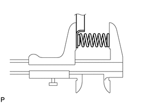
Using a vernier caliper, measure the free length of the spring together with the spring seat.
Standard Free Length 20.76 mm (0.817 in.) If the free length is shorter than the standard free length, replace the direct clutch return spring sub-assembly.
-
-
INSPECT PACK CLEARANCE OF NO. 2 CLUTCH
-
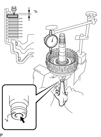
Text in Illustration *a Oil Hole *b Distance A Using a dial indicator, measure the moving distance (distance A) of the No. 2 clutch flange at both ends across the diameter while blowing compressed air (196 kPa, 2.0 kgf/cm2, 28 psi) from the oil hole as shown in the illustration, and calculate the average.
Standard Clearance 1.05 to 1.25 mm (0.0414 to 0.0492 in.) -
If the pack clearance is outside the standard range, select and install a No. 2 clutch flange that brings the pack clearance within the standard range.
Tech Tips
There are 9 types of No. 2 clutch flanges that can be used to adjust the pack clearance. Select the one with the most appropriate thickness.
No. 2 Clutch Flange Thickness Part No. Mark Thickness 35635-50181 40 3.95 to 4.05 mm (0.1556 to 0.1594 in.) 35635-50231 41 4.05 to 4.15 mm (0.1595 to 0.1633 in.) 35635-50191 42 4.15 to 4.25 mm (0.1634 to 0.1673 in.) 35635-50241 43 4.25 to 4.35 mm (0.1674 to 0.1712 in.) 35635-50201 44 4.35 to 4.45 mm (0.1713 to 0.1751 in.) 35635-50251 45 4.45 to 4.55 mm (0.1752 to 0.1791 in.) 35635-50211 46 4.55 to 4.65 mm (0.1792 to 0.1830 in.) 35635-50261 47 4.65 to 4.75 mm (0.1831 to 0.1870 in.) 35635-50221 48 4.75 to 4.85 mm (0.1871 to 0.1909 in.)
-
-
INSPECT INDIVIDUAL PISTON OPERATION
-
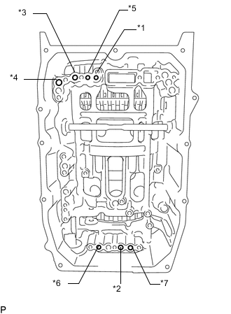
Text in Illustration *1 Forward Clutch *2 Direct Clutch *3 Overdrive Clutch *4 Reverse Clutch *5 No. 1 Brake *6 No. 2 Brake (IN) *7 No. 2 Brake (OUT) Check the operating sound while applying compressed air into the oil holes indicated in the illustration.
-
-
INSPECT AUTOMATIC TRANSMISSION CASE SUB-ASSEMBLY
-
Using a caliper gauge, measure the inside diameter of the automatic transmission case sleeve bush.
Standard Inside Diameter 51.470 to 51.555 mm (2.027 to 2.029 in.) If the inside diameter is not as specified, replace the automatic transmission case sub-assembly.
-