SHIFT LEVER REASSEMBLY
CAUTION / NOTICE / HINT
Tech Tips
-
Use the same procedure for RHD and LHD vehicles.
-
The procedure listed below is for LHD vehicles.
PROCEDURE
-
INSTALL POSITION INDICATOR LENS
Tech Tips
Only perform this procedure when replacement of the position indicator lens is necessary.
-
Attach the 4 claws to install the position indicator lens to the position indicator housing assembly.
-
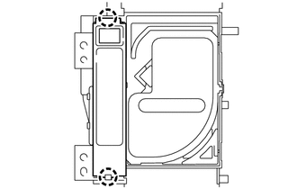
Attach the 2 claws install the position indicator plate sub-assembly to the position indicator lens.
-
Attach the claw and install the No. 2 position indicator slide cover to the position indicator slide cover.
-
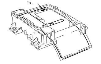
Text in Illustration *a "FRONT" Mark Install the position indicator slide cover together with the No. 2 position indicator slide cover.
Tech Tips
Install the position indicator slide cover so that its mark faces the vehicle front.
-
Attach the 2 claws to install the shift lock release spring and shift lock release button to the position indicator housing assembly.
-
Install the position indicator housing assembly Click here.
-
-
INSTALL SHIFT LOCK CONTROL ECU SUB-ASSEMBLY
-
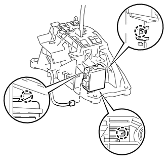
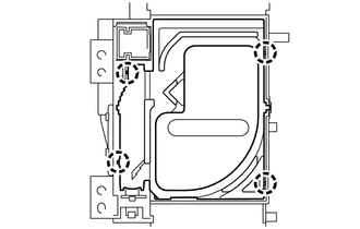
Attach the 3 claws to install the shift lock control ECU sub-assembly to the lower shift lever assembly.
-
Connect the shift lock solenoid connector.
-
-
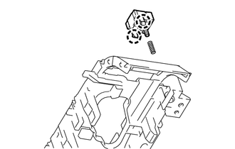
INSTALL NO. 2 INDOOR ELECTRICAL KEY ANTENNA ASSEMBLY
-
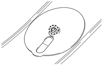
Install the No. 2 indoor electrical key antenna assembly to the lower shift lever assembly with the screw.
- Torque:
- 1.9 N*m { 19 kgf*cm, 16 in.*lbf }
-