AUTOMATIC TRANSMISSION UNIT DISASSEMBLY

PROCEDURE
-
REMOVE TRANSMISSION BREATHER HOSE SUB-ASSEMBLY
-
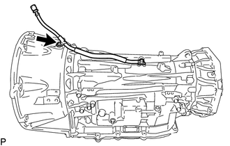
Remove the bolt and transmission breather hose sub-assembly from the automatic transmission case sub-assembly.
-
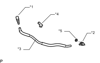
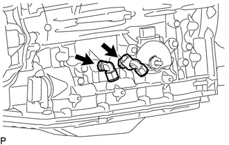
Text in Illustration *1 No. 2 Breather Plug *2 No. 1 Breather Plug *3 Breather Plug Hose *4 Clamp *5 Breather Plug O-ring Remove the clamp from the breather plug hose.
-
Remove the No. 1 breather plug and No. 2 breather plug from the breather plug hose.
-
Remove the breather plug O-ring from the No. 1 breather plug.
-
-
REMOVE AUTOMATIC TRANSMISSION HOUSING
-
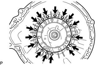
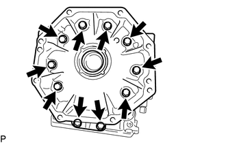
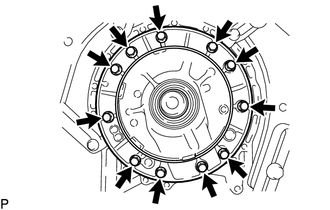
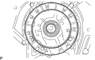
Remove the 16 bolts and automatic transmission housing from the automatic transmission case sub-assembly.
-
-
FIX AUTOMATIC TRANSMISSION ASSEMBLY
-
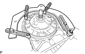
Install the automatic transmission assembly to an overhaul attachment.
-
-
REMOVE REAR TRANSFER ADAPTER
-
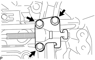
Remove the 10 bolts.
-
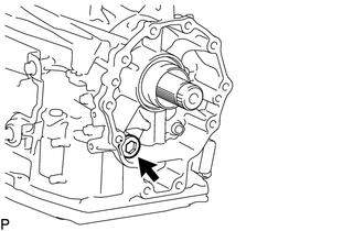
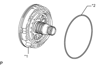
Remove the rear transfer adapter.
Tech Tips
Tap on the circumference of the rear transfer adapter with a plastic-faced hammer to remove the rear transfer adapter.
-
Remove the O-ring from the rear transfer adapter.
-
-
REMOVE TRANSFER CASE ADAPTER REAR OIL SEAL
-
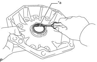
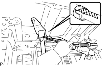
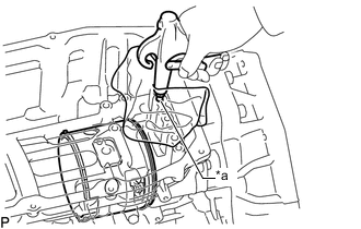
Text in Illustration *a Protective Tape Using a screwdriver, pry out the transfer case adapter rear oil seal.
Note
Be careful not to damage the rear transfer adapter.
Tech Tips
Tape the screwdriver tip before use.
-
-
REMOVE PARK/NEUTRAL POSITION SWITCH ASSEMBLY
-
REMOVE OIL COOLER TUBE UNION
-
Remove the 2 oil cooler tube unions from the automatic transmission case sub-assembly.
-
Remove the 2 O-rings from the 2 oil cooler tube unions.
-
-
REMOVE REFILL PLUG
-
Remove the refill plug from the automatic transmission case sub-assembly.
-
Remove the O-ring from the refill plug.
-
-
REMOVE AUTOMATIC TRANSMISSION CASE PLUG
-
for T55H "TORX" Type:
-
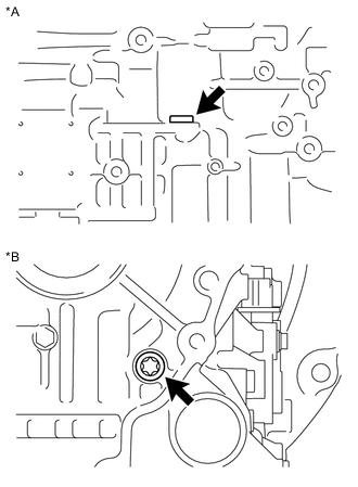
Text in Illustration *A for LH Side *B for Rear Side Using a T55H "TORX" socket wrench, remove the 2 automatic transmission case plugs from the automatic transmission case sub-assembly.
-
Remove the 2 O-rings from the 2 automatic transmission case plugs.
-
-
for 17 mm Hexagon Type:
-
Remove the automatic transmission case plug from the automatic transmission case sub-assembly.
-
Remove the O-ring from the automatic transmission case plug.
-
-
-
REMOVE AUTOMATIC TRANSMISSION OIL PAN SUB-ASSEMBLY
-
REMOVE VALVE BODY OIL STRAINER ASSEMBLY
-
REMOVE TRANSMISSION VALVE BODY ASSEMBLY
-
REMOVE TRANSMISSION WIRE
-
REMOVE TRANSMISSION REVOLUTION SENSOR (SP2)
-
REMOVE PARKING LOCK PAWL BRACKET
-
Remove the 3 bolts and parking lock pawl bracket.
-
-
REMOVE MANUAL VALVE LEVER SUB-ASSEMBLY
-
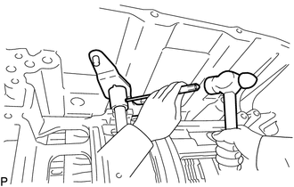
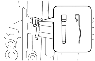
Text in Illustration *a Protective Tape Using a screwdriver and hammer, cut off the spacer and remove it from the manual valve lever sub-assembly.
Note
Be careful not to damage the manual valve lever sub-assembly.
Tech Tips
Tape the screwdriver tip before use.
-
Using a 3 mm pin punch and a hammer, remove the spring pin.
Tech Tips
Slowly tap out the spring pin so that it does not fall into the automatic transmission case sub-assembly.
-
Remove the manual valve lever shaft and manual valve lever sub-assembly from the automatic transmission case sub-assembly.
-
-
REMOVE PARKING LOCK ROD SUB-ASSEMBLY
-
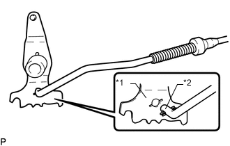
Text in Illustration *1 Manual Valve Lever Sub-assembly *2 Parking Lock Rod Sub-assembly Remove the parking lock rod sub-assembly from the manual valve lever sub-assembly.
-
-
REMOVE PARKING LOCK PAWL SHAFT
-
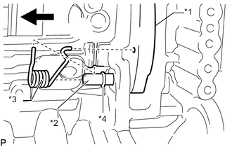
Text in Illustration *1 Parking Lock Pawl *2 Parking Lock Pawl Shaft *3 Spring *4 E-ring Remove the parking lock pawl shaft, parking lock pawl and spring.
-
Remove the E-ring from the parking lock pawl shaft.
-
-
REMOVE MANUAL VALVE LEVER SHAFT OIL SEAL
-
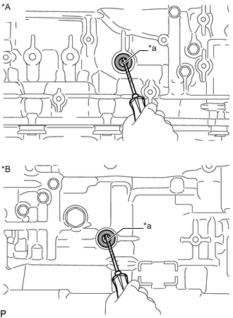
Text in Illustration *A for RH Side *B for LH Side *a Protective Tape Using a screwdriver, pry out the 2 manual valve lever shaft oil seals.
Note
Be careful not to damage the automatic transmission case sub-assembly.
Tech Tips
Tape the screwdriver tip before use.
-
-
REMOVE MANUAL DETENT SPRING SUB-ASSEMBLY
-
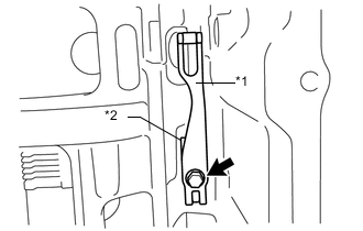
Text in Illustration *1 Manual Detent Spring Sub-assembly *2 Manual Detent Spring Cover Remove the bolt, manual detent spring sub-assembly and manual detent spring cover.
-
-
REMOVE OIL PUMP ASSEMBLY
-
Remove the 11 bolts from the oil pump assembly.
-
Pull out the oil pump assembly from the automatic transmission case sub-assembly.
Note
Do not damage the oil pump assembly.
-
Text in Illustration *1 Oil Pump Assembly *2 Oil Pump O-ring Remove the oil pump O-ring from the oil pump assembly.
-
-
REMOVE OVERDRIVE BRAKE PLATE STOPPER SPRING
-
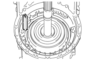
Remove the overdrive brake plate stopper spring from the automatic transmission case sub-assembly.
-
-
REMOVE OVERDRIVE AND REVERSE MULTIPLE DISC CLUTCH ASSEMBLY AND FRONT PLANETARY GEAR ASSEMBLY WITH NO. 1 BRAKE DISC SET
-
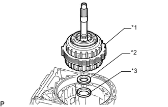
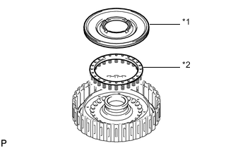
Text in Illustration *1 Overdrive and Reverse Multiple Disc Clutch Assembly and Front Planetary Gear Assembly with No. 1 Brake Disc Set *2 Thrust Needle Roller Bearing *3 Thrust Bearing Race Remove the overdrive and reverse multiple disc clutch assembly and front planetary gear assembly with No. 1 brake disc set from the automatic transmission case sub-assembly.
-
Remove the thrust needle roller bearing and thrust bearing race from the automatic transmission case sub-assembly.
-
Remove the snap ring from the automatic transmission case sub-assembly.
-
-
REMOVE NO. 1 BRAKE DISC SET
-
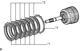
Text in Illustration *1 No. 1 Brake Plate *2 No. 1 Brake Disc *3 No. 1 Brake Flange Remove the 6 No. 1 brake plates, 6 No. 1 brake discs and No. 1 brake flange.
-
-
INSPECT NO. 1 BRAKE DISC
-
REMOVE FRONT PLANETARY GEAR ASSEMBLY
-
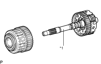
Text in Illustration *1 Front Planetary Gear Assembly Remove the front planetary gear assembly together with the planetary sun gear from the overdrive and reverse multiple disc clutch assembly.
-
Text in Illustration *1 Front Planetary Sun Gear Remove the front planetary sun gear from the front planetary gear assembly.
-
Text in Illustration *1 Planetary Carrier Thrust Washer Remove the planetary carrier thrust washer from the front planetary gear assembly.
-
Text in Illustration *1 Oil Seal Ring Remove the 3 oil seal rings from the front planetary gear assembly.
-
Text in Illustration *1 Oil Seal Ring Remove the 2 oil seal rings from the front planetary gear assembly.
-
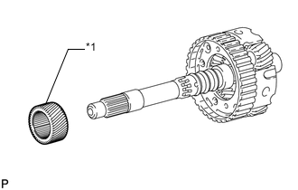
Text in Illustration *1 Front Planetary Gear Radial Needle Roller Bearing Remove the front planetary gear radial needle roller bearing from the front planetary gear assembly.
-
-
INSPECT FRONT PLANETARY GEAR ASSEMBLY
-
REMOVE NO. 3 CLUTCH DISC SET
-
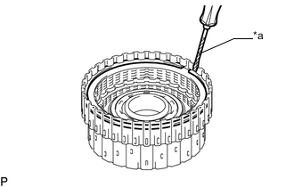
Text in Illustration *a Protective Tape Using a screwdriver, remove the snap ring from the reverse clutch drum sub-assembly.
Note
Be careful not to damage the reverse clutch drum sub-assembly.
Tech Tips
Tape the screwdriver tip before use.
-
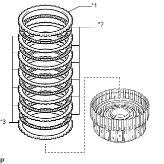
Text in Illustration *1 No. 3 Clutch Flange *2 No. 3 Clutch Discs *3 No. 3 Clutch Plate Remove the No. 3 clutch flange, 6 No. 3 clutch discs and 6 No. 3 clutch plates from the reverse clutch drum sub-assembly.
-
-
INSPECT NO. 3 CLUTCH DISC
-
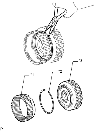
REMOVE OVERDRIVE DIRECT CLUTCH DISC
-
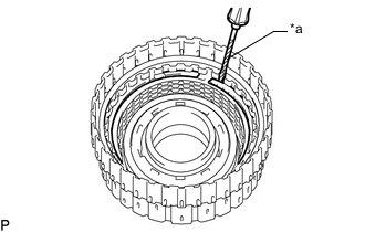
Text in Illustration *a Protective Tape Using a screwdriver, remove the snap ring from the overdrive direct clutch drum sub-assembly.
Note
Be careful not to damage the overdrive direct clutch drum sub-assembly.
Tech Tips
Tape the screwdriver tip before use.
-
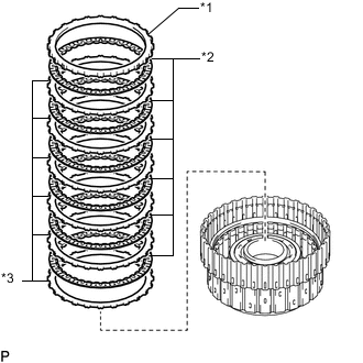
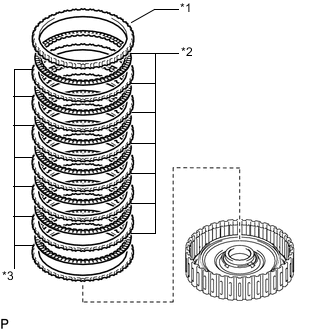
Text in Illustration *1 Overdrive Clutch Flange *2 Overdrive Direct Clutch Disc *3 Overdrive Direct Clutch Plate Remove the overdrive clutch flange, 6 overdrive direct clutch discs and 6 overdrive direct clutch plates from the overdrive direct clutch drum sub-assembly.
-
-
INSPECT OVERDRIVE DIRECT CLUTCH DISC
-
REMOVE NO. 4 CLUTCH PISTON
-
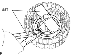
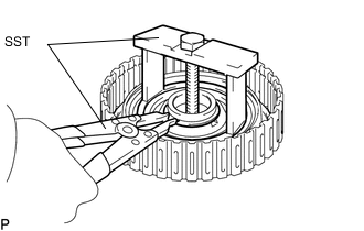
Place SST on the reverse clutch balancer, and compress the reverse clutch return spring sub-assembly (rear) with a press.
- SST
- 09380-50010 ( 09381-05020 )
-
Using SST, remove the snap ring.
- SST
- 09350-30020 ( 09350-07070 )
-
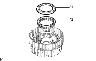
Text in Illustration *1 Reverse Clutch Balancer *2 Reverse Clutch Return Spring Sub-assembly (Rear) Remove the reverse clutch balancer and reverse clutch return spring sub-assembly (rear) from the overdrive direct clutch drum sub-assembly.
-
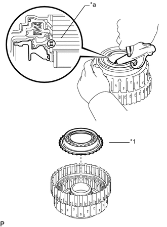
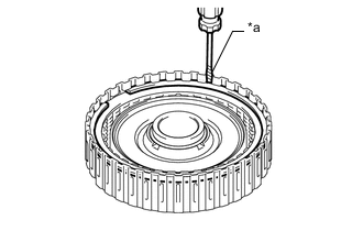
Text in Illustration *1 No. 4 Clutch Piston *a Oil Hole While holding the overdrive direct clutch drum sub-assembly, apply compressed air to the oil hole to remove the No. 4 clutch piston.
-
Remove the O-ring from the No. 4 clutch piston.
-
-
INSPECT REVERSE CLUTCH RETURN SPRING SUB-ASSEMBLY (REAR)
-
REMOVE OVERDRIVE DIRECT CLUTCH DRUM SUB-ASSEMBLY
-
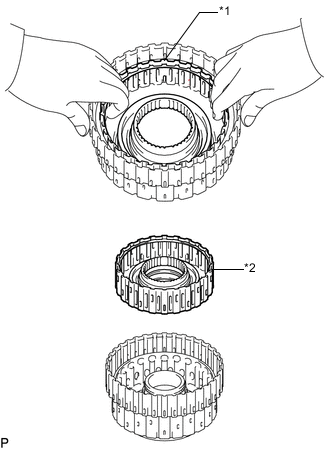
Text in Illustration *1 Snap Ring *2 Overdrive Direct Clutch Drum Sub-assembly Remove the overdrive direct clutch drum sub-assembly from the reverse clutch drum sub-assembly.
Tech Tips
If the overdrive direct clutch drum sub-assembly is difficult to remove, reinstall the snap ring for the overdrive direct clutch discs.
-
Remove the 3 O-rings from the overdrive direct clutch drum sub-assembly.
-
-
REMOVE REVERSE CLUTCH PISTON SUB-ASSEMBLY
-
Place SST on the No. 3 clutch balancer, and compress the reverse clutch return spring sub-assembly (front) with a press.
- SST
- 09380-50010 ( 09381-05020 )
-
Using SST, remove the snap ring.
- SST
- 09350-30020 ( 09350-07070 )
-
Text in Illustration *1 No. 3 Clutch Balancer *2 Reverse Clutch Return Spring Sub-assembly (Front) Remove the No. 3 clutch balancer and reverse clutch return spring sub-assembly (front).
-
Remove the O-ring from the No. 3 clutch balancer.
-
Text in Illustration *1 Reverse Clutch Piston Sub-assembly *a Oil Hole Hold the reverse clutch drum sub-assembly and apply compressed air to the oil hole of the reverse clutch drum sub-assembly to remove the reverse clutch piston sub-assembly.
-
Remove the O-ring from the reverse clutch piston sub-assembly.
-
Remove the O-ring from the reverse clutch drum sub-assembly.
-
-
INSPECT REVERSE CLUTCH RETURN SPRING SUB-ASSEMBLY (FRONT)
-
INSPECT REVERSE CLUTCH DRUM SUB-ASSEMBLY
-
REMOVE FORWARD MULTIPLE DISC CLUTCH ASSEMBLY WITH FRONT PLANETARY RING GEAR
-
Text in Illustration *1 Forward Multiple Disc Clutch Assembly with Front Planetary Ring Gear *2 Thrust Needle Roller Bearing *3 Thrust Bearing Race Remove the forward multiple disc clutch assembly with front planetary ring gear, thrust needle roller bearing and thrust bearing race from the automatic transmission case sub-assembly.
-
-
REMOVE FRONT PLANETARY RING GEAR
-
Text in Illustration *1 Front Planetary Ring Gear *2 Snap Ring *3 Forward Multiple Disc Clutch Assembly Using needle-nose pliers, detach the snap ring and remove the front planetary ring gear and snap ring from the forward multiple disc clutch assembly.
-
-
REMOVE FORWARD MULTIPLE CLUTCH DISC SET
-
Text in Illustration *a Protective Tape Using a screwdriver, remove the snap ring.
Note
Be careful not to damage the forward multiple clutch disc assembly.
Tech Tips
Tape the screwdriver tip before use.
-
Text in Illustration *1 Forward Clutch Flange *2 Forward Multiple Clutch Disc *3 Forward Multiple Clutch Plate Remove the forward clutch flange, 7 forward multiple clutch discs and 7 forward multiple clutch plates.
-
-
INSPECT FORWARD MULTIPLE CLUTCH DISC
-
REMOVE FORWARD CLUTCH PISTON
-
Place SST on the No. 1 clutch balancer, and compress the forward clutch return spring sub-assembly with a press.
- SST
- 09380-50010 ( 09381-05020 )
-
Using SST, remove the snap ring.
- SST
- 09350-30020 ( 09350-07070 )
-
Text in Illustration *1 No. 1 Clutch Balancer *2 Forward Clutch Return Spring Sub-assembly Remove the No. 1 clutch balancer and forward clutch return spring sub-assembly from the forward clutch drum sub-assembly.
-
Remove the O-ring from the No. 1 clutch balancer.
-
Text in Illustration *a Oil Hole Hold the forward clutch drum sub-assembly and apply compressed air to the oil hole of the forward clutch drum sub-assembly to remove the forward clutch piston.
-
Remove the 2 O-rings from the forward clutch piston.
-
-
INSPECT FORWARD CLUTCH RETURN SPRING SUB-ASSEMBLY
-
INSPECT FORWARD CLUTCH DRUM SUB-ASSEMBLY
-
REMOVE FORWARD MULTIPLE DISC CLUTCH HUB
-
Text in Illustration *1 Forward Multiple Disc Clutch Hub *2 Thrust Bearing Race *3 Thrust Needle Roller Bearing Remove the forward multiple disc clutch hub from the automatic transmission case sub-assembly.
-
Remove the thrust bearing race and thrust needle roller bearing from the automatic transmission case sub-assembly.
-
-
REMOVE SUN GEAR INPUT DRUM SUB-ASSEMBLY
-
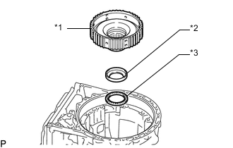
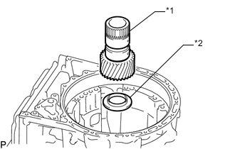
Text in Illustration *1 Sun Gear Input Drum Sub-assembly *2 Thrust Needle Roller Bearing *3 Thrust Bearing Race Remove the sun gear input drum sub-assembly, thrust needle roller bearing and thrust bearing race from the automatic transmission case sub-assembly.
-
-
INSPECT SUN GEAR INPUT DRUM SUB-ASSEMBLY
-
REMOVE REAR PLANETARY SUN GEAR SUB-ASSEMBLY
-
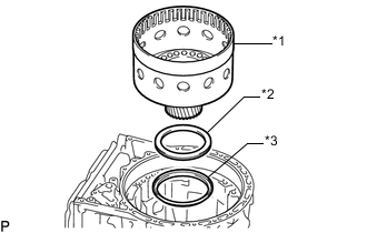
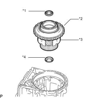
Text in Illustration *1 Rear Planetary Sun Gear Sub-assembly *2 Thrust Bearing Race Remove the rear planetary sun gear sub-assembly and thrust bearing race from the automatic transmission case sub-assembly.
-
-
INSPECT REAR PLANETARY SUN GEAR SUB-ASSEMBLY
-
REMOVE ONE-WAY CLUTCH OUTER RACE WITH NO. 1 ONE-WAY CLUTCH
-
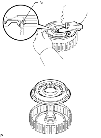
Using SST, remove the snap ring from the automatic transmission case sub-assembly.
- SST
- 09350-30020 ( 09350-07060 )
-
Text in Illustration *1 Thrust Needle Roller Bearing *2 One-way Clutch Outer Race with No. 1 One-way Clutch *3 Rear Planetary Gear Assembly *4 Thrust Bearing Race Remove the thrust needle roller bearing, rear planetary gear assembly, one-way clutch outer race with No. 1 one-way clutch and thrust bearing race from the automatic transmission case sub-assembly.
-
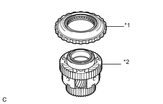
Text in Illustration *1 One-way Clutch Outer Race with No. 1 One-way Clutch *2 Rear Planetary Gear Assembly Remove the one-way clutch outer race with No. 1 one-way clutch from the rear planetary gear assembly.
-
-
INSPECT NO. 1 ONE-WAY CLUTCH
-
REMOVE NO. 1 ONE-WAY CLUTCH
-
Text in Illustration *1 Snap Ring *2 No. 1 One-way Clutch *3 One-way Clutch Outer Race Remove the snap ring and No. 1 one-way clutch from the one-way clutch outer race.
-
-
INSPECT REAR PLANETARY GEAR ASSEMBLY
-
REMOVE NO. 2 BRAKE DISC SET
-
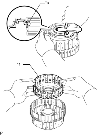
Remove the snap ring from the automatic transmission case sub-assembly.
-
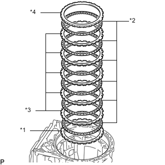
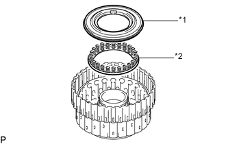
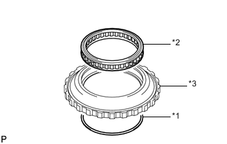
Text in Illustration *1 Brake Plate *2 No. 2 Brake Disc *3 No. 2 Brake Plate *4 No. 2 Brake Flange Remove the brake plate, 6 No. 2 brake discs, 5 No. 2 brake plates and No. 2 brake flange from the automatic transmission case sub-assembly.
-
-
INSPECT NO. 2 BRAKE DISC
-
REMOVE DIRECT MULTIPLE DISC CLUTCH ASSEMBLY WITH REAR PLANETARY RING GEAR AND OUTPUT SHAFT SUB-ASSEMBLY
-
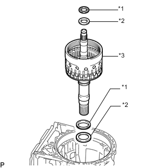
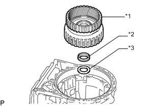
Text in Illustration *1 Thrust Needle Roller Bearing *2 Thrust Bearing Race *3 Direct Multiple Disc Clutch Assembly with Rear Planetary Ring Gear and Output Shaft Sub-assembly Remove the 2 thrust needle roller bearings, 2 thrust bearing races and direct multiple disc clutch assembly with rear planetary ring gear and output shaft sub-assembly from the automatic transmission case sub-assembly.
-
-
REMOVE REAR PLANETARY RING GEAR
-
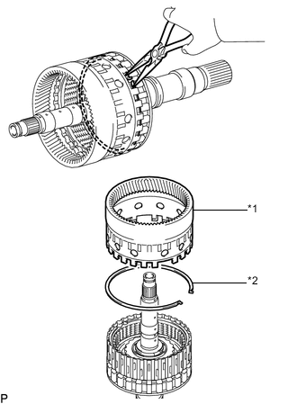
Text in Illustration *1 Rear Planetary Ring Gear *2 Snap Ring Using needle-nose pliers, detach the snap ring and remove the rear planetary ring gear from the output shaft sub-assembly.
-
-
REMOVE DIRECT MULTIPLE DISC CLUTCH ASSEMBLY
-
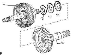
Text in Illustration *1 Direct Multiple Disc Clutch Assembly *2 Thrust Needle Roller Bearing *3 Thrust Bearing Race *4 Output Shaft Sub-assembly Remove the direct multiple disc clutch assembly from the output shaft sub-assembly.
-
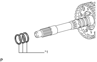
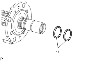
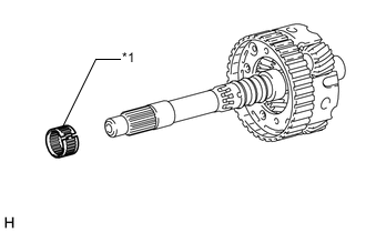
Remove the thrust needle roller bearing and 2 thrust bearing races from the output shaft sub-assembly.
-
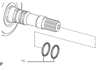
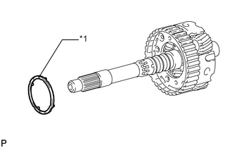
Text in Illustration *1 Oil Seal Ring Remove the 2 oil seal ring from the output shaft sub-assembly.
-
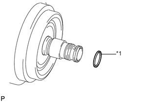
Text in Illustration *1 Oil Seal Ring Remove the oil seal ring from the direct multiple disc clutch assembly.
-
-
REMOVE NO. 2 CLUTCH DISC SET
-
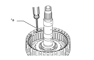
Text in Illustration *a Protective Tape Using a screwdriver, remove the snap ring from the direct clutch drum sub-assembly.
Note
Be careful not to damage the direct clutch drum sub-assembly.
Tech Tips
Tape the screwdriver tip before use.
-
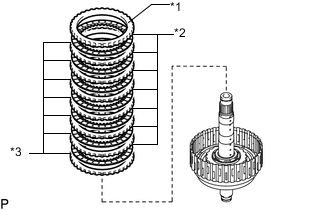
Text in Illustration *1 No. 2 Clutch Flange *2 No. 2 Clutch Disc *3 No. 2 Clutch Plate Remove the No. 2 clutch flange, 7 No. 2 clutch discs and 7 No. 2 clutch plates from the direct clutch drum sub-assembly.
-
-
INSPECT NO. 2 CLUTCH DISC
-
REMOVE DIRECT CLUTCH PISTON
-
Place SST on the No. 2 clutch balancer, and compress the direct clutch return spring sub-assembly with a press.
- SST
- 09387-00020
-
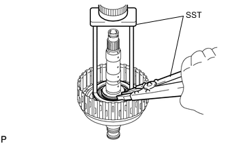
Using SST, remove the snap ring.
- SST
- 09350-30020 ( 09350-07070 )
-
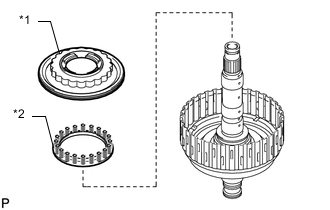
Text in Illustration *1 No. 2 Clutch Balancer *2 Direct Clutch Return Spring Sub-assembly Remove the No. 2 clutch balancer and direct clutch return spring sub-assembly from the direct clutch drum sub-assembly.
-
Remove the O-ring from the No. 2 clutch balancer.
-
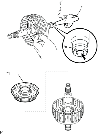
Text in Illustration *1 Direct Clutch Piston *a Oil Hole Hold the direct clutch drum sub-assembly and apply compressed air to the oil hole of the direct clutch drum sub-assembly to remove the direct clutch piston.
-
Remove the O-ring from the direct clutch piston.
-
Remove the O-ring from the direct clutch drum sub-assembly.
-
-
INSPECT DIRECT CLUTCH RETURN SPRING SUB-ASSEMBLY
-
REMOVE NO. 2 BRAKE PISTON
-
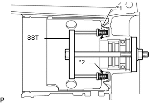
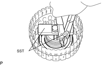
Text in Illustration *1 No. 2 Brake Piston Return Spring Sub-assembly *2 Snap Ring Set SST on the No. 2 brake piston return spring sub-assembly, tighten SST and compress the No. 2 brake piston return spring sub-assembly.
- SST
- 09380-50010 ( 09381-05010, 09381-05020, 09381-05030, 09381-05040, 09381-05050 )
-
Using SST, remove the snap ring and the No. 2 brake piston return spring sub-assembly.
- SST
- 09350-30020 ( 09350-07070 )
-
Text in Illustration *a Oil Hole Apply compressed air to the oil hole of the automatic transmission case sub-assembly to remove the No. 2 brake piston from the automatic transmission case sub-assembly.
-
Remove the 3 O-rings from the No. 2 brake piston.
-
-
INSPECT NO. 2 BRAKE PISTON RETURN SPRING SUB-ASSEMBLY
-
REMOVE 1ST AND REVERSE BRAKE PLATE STOPPER SPRING
-
Remove the 1st and reverse brake plate stopper spring from the automatic transmission case sub-assembly.
-
-
REMOVE OUTPUT SHAFT REAR RADIAL BALL BEARING
-
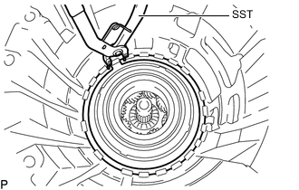
Using snap ring pliers, remove the snap ring from the automatic transmission case sub-assembly.
-
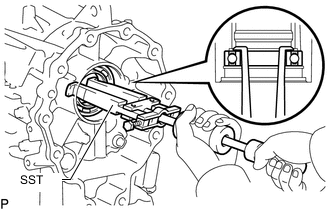
Using SST, remove the output shaft rear radial ball bearing.
- SST
- 09308-00010
-