AUTOMATIC TRANSMISSION SYSTEM TCM Power Source Circuit
DESCRIPTION
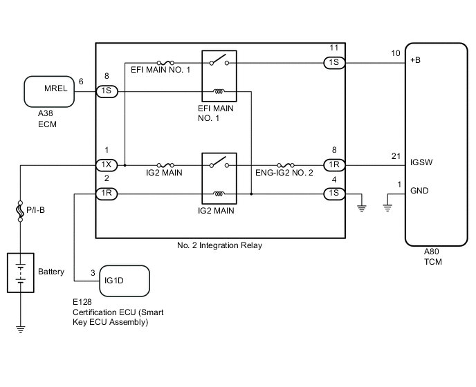
When the engine switch is turned on (IG), the battery voltage is applied to the IGSW of the TCM. The output signal from the MREL terminal of the ECM causes a current to flow to the coil, closing the contacts of the EFI MAIN NO. 1 relay and supplying power to terminal +B of the TCM.
WIRING DIAGRAM
CAUTION / NOTICE / HINT
Note
Inspect the fuses for circuits related to this system before performing the following procedure.
PROCEDURE
-
CHECK HARNESS AND CONNECTOR (TCM - BODY GROUND)
-
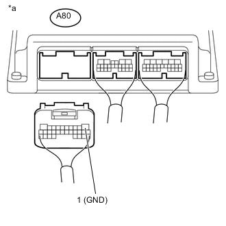
Text in Illustration *a Rear view of wire harness connector
(to TCM)
Disconnect the TCM connector.
-
Measure the resistance according to the value(s) in the table below.
Standard Resistance Tester Connection Condition Specified Condition A80-1 (GND) - Body ground Always Below 1 Ω
NG 
REPAIR OR REPLACE HARNESS OR CONNECTOR
OK 
-
-
CHECK HARNESS AND CONNECTOR (NO. 2 INTEGRATION RELAY - TCM)
-
Disconnect the No. 2 integration relay 1R and 1S connectors.
-
Disconnect the A80 TCM connector.
-
Measure the resistance according to the value(s) in the table below.
Standard Resistance Tester Connection Condition Specified Condition 1S-11 - A80-10 (+B) Always Below 1 Ω 1R-8 - A80-21 (IGSW) Always Below 1 Ω 1S-11 or A80-10 (+B) - Body ground Always 10 kΩ or higher 1R-8 or A80-21 (IGSW) - Body ground Always 10 kΩ or higher
OK
GO TO ECM POWER SOURCE CIRCUIT (ENGINE CONTROL SYSTEM / SFI SYSTEM) Click here
NG
REPAIR OR REPLACE HARNESS OR CONNECTOR
-