AUTOMATIC TRANSMISSION ASSEMBLY INSTALLATION

PROCEDURE
-
INSPECT TORQUE CONVERTER ASSEMBLY
-
INSTALL TORQUE CONVERTER ASSEMBLY
-
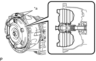
Text in Illustration *a Matchmarks Engage the splines of the input shaft and turbine runner.
-
Engage the splines of the stator shaft and stator while turning the torque converter assembly.
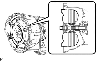
Tech Tips
If the stator shaft splines are difficult to engage with the stator splines, move the torque converter back approximately 10 mm and engage the splines while rotating the torque converter.
-
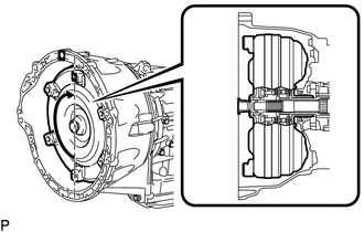
Turn the torque converter assembly to engage the key of the oil pump drive gear and the slot on the torque converter assembly.
-
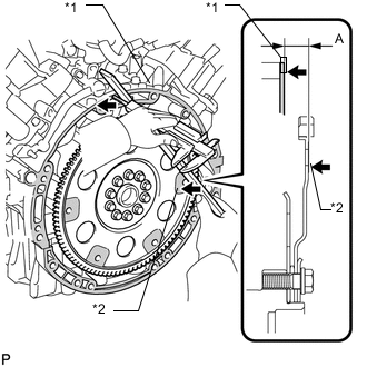
Text in Illustration *1 Engine Surface *2 Drive Plate Surface Using a vernier caliper and straightedge, measure dimension A between the surface of the engine that contacts the transmission and the surface of the drive plate that contacts the torque converter.
Note
Make sure to deduct the thickness of the straightedge.
-
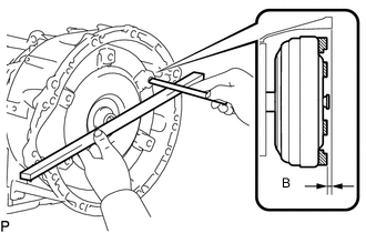
Using a vernier caliper and a straightedge, measure dimension B shown in the illustration and check that B is more than A measured in the first step.
Standard distance B = A + 1.00 mm (0.0394 in.) or more Note
-
Make sure to deduct the thickness of the straightedge.
-
If the transmission is installed to the engine with the torque converter not sufficiently inserted, the torque converter may be damaged.
-
-
-
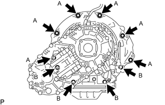
INSTALL WIRE HARNESS CLAMP BRACKET
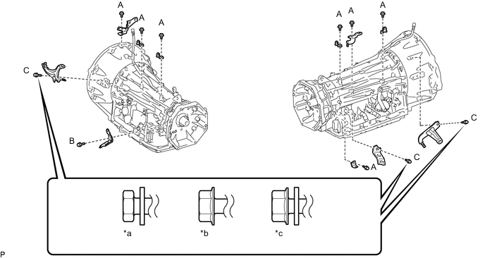
Text in Illustration *a for Type A *b for Type B *c for Type C - -
-
Install the 11 bolts and 11 wire harness clamp brackets.
- Torque:
- Bolt A
- 8.0 N*m { 82 kgf*cm, 71 in.*lbf }
- Bolt B
- 29 N*m { 296 kgf*cm, 21 ft.*lbf }
- Bolt C (for Type A)
- 7.5 N*m { 76 kgf*cm, 66 in.*lbf }
- Bolt C (for Type B)
- 8.0 N*m { 82 kgf*cm, 71 in.*lbf }
- Bolt C (for Type C)
- 13 N*m { 132 kgf*cm, 10 ft.*lbf }
Note
Check whether the bolt being used is Type A or Type B or Type C, and then tighten the bolt using the appropriate torque.
-
-
INSTALL AUTOMATIC TRANSMISSION ASSEMBLY
-
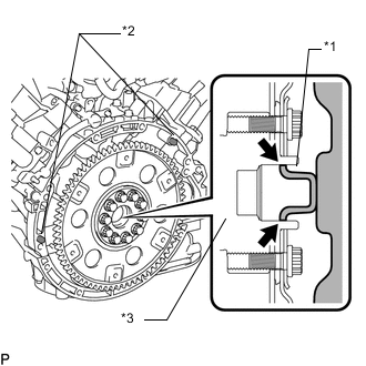
Text in Illustration *1 Torque Converter Centerpiece *2 Knock Pin *3 Crankshaft 
Clutch Spline Grease Apply clutch spline grease to the surface of the crankshaft that contacts the torque converter centerpiece.
Clutch spline grease Toyota Genuine Clutch Spline Grease or equivalent Maximum grease amount Approximately 1 g (0.0353 oz.) -
Confirm that the 2 knock pins are on the surface of the engine block that contacts the transmission.
-
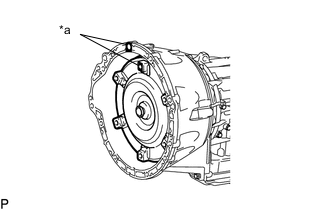
Text in Illustration *a Matchmarks Make sure that the mark is positioned as shown in the illustration.
-
Keeping the engine and automatic transmission assembly horizontal, align the knock pins with the holes on the automatic transmission assembly and install the 10 bolts shown in the illustration.
- Torque:
- for bolt A
- 71 N*m { 724 kgf*cm, 52 ft.*lbf }
- for bolt B
- 37 N*m { 377 kgf*cm, 27 ft.*lbf }
-
-
INSTALL TRANSFER ASSEMBLY
-
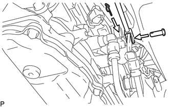
CONNECT WIRE HARNESS AND CONNECTOR
-
Connect the park/neutral position switch connector, 2 transmission wire connectors and 3 transfer control connectors.
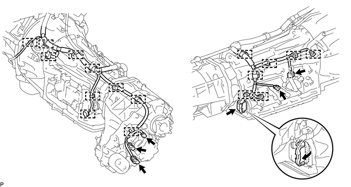
Tech Tips
Push up the lever until the claw of the transmission wire connector makes a connection sound.
-
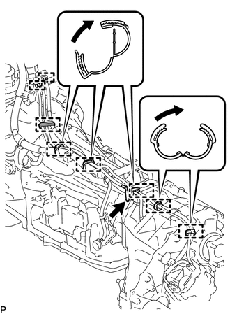
Attach the 17 clamps and connect the wire harness.
-
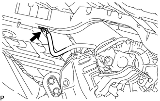
Connect the transfer breather hose sub-assembly to the automatic transmission assembly.
-
Attach the 6 clamps 2 hose plugs and connect the transfer breather hose sub-assembly.
-
Tilt up the automatic transmission.
-
-
INSTALL REAR NO. 1 ENGINE MOUNTING INSULATOR
-
Install the rear No. 1 engine mounting insulator to the transmission with the 4 bolts.
- Torque:
- 59 N*m { 602 kgf*cm, 44 ft.*lbf }
-
Install the engine mounting heat insulator with the 2 bolts.
- Torque:
- 12 N*m { 122 kgf*cm, 9 ft.*lbf }
-
-
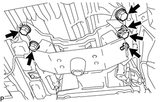
INSTALL NO. 2 FRAME CROSSMEMBER SUB-ASSEMBLY
-
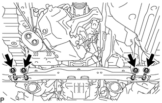
Temporarily install the No. 2 frame crossmember sub-assembly to the frame with the 4 bolts and 4 nuts.
-
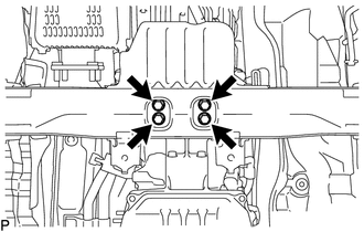
Lower the transmission assembly, and then install the rear No. 1 engine mounting insulator to the No. 2 frame crossmember sub-assembly with the 4 bolts.
- Torque:
- 37 N*m { 377 kgf*cm, 27 ft.*lbf }
-
Tighten the No. 2 frame crossmember sub-assembly with the 4 bolts and 4 nuts.
- Torque:
- 110 N*m { 1122 kgf*cm, 81 ft.*lbf }
-
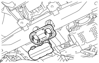
w/ Cover:
Install the engine mounting hole cover.
-
-
CONNECT GROUND CABLE
-
Connect the ground cable with the bolt.
- Torque:
- 8.4 N*m { 85 kgf*cm, 74 in.*lbf }
-
-
CONNECT OIL COOLER TUBE
-
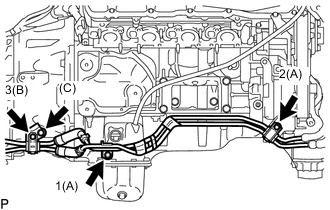
Install the transmission oil cooler tube clamp sub-assembly with bolt (labeled C).
- Torque:
- 14 N*m { 143 kgf*cm, 10 ft.*lbf }
-
Temporarily install the oil cooler tube with the 3 bolts and 2 oil cooler tube unions.
-
Tighten the 3 bolts in the sequence shown in the illustration.
- Torque:
- for bolt A
- 14 N*m { 143 kgf*cm, 10 ft.*lbf }
- for bolt B
- 8.0 N*m { 82 kgf*cm, 71 in.*lbf }
-
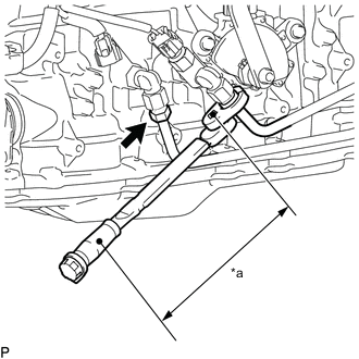
Text in Illustration *a Torque Wrench Fulcrum Length Tighten the 2 oil cooler tubes.
- Torque:
- Specified tightening torque
- 34 N*m { 347 kgf*cm, 25 ft.*lbf }
Tech Tips
-
Calculate the torque wrench reading when changing the fulcrum length of the torque wrench.
-
When using 17 mm union nut wrench (fulcrum length of 30 mm (1.18 in.)) + torque wrench (fulcrum length of 180 mm (7.09 in.)): 29 N*m (297 kgf*cm, 21 ft.*lbf)
-
-
INSTALL DRIVE PLATE AND TORQUE CONVERTER SETTING BOLT
-
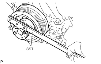
Using SST, hold the crankshaft.
- SST
- 09213-70011 ( 09213-70020 )
- 09330-00021
-
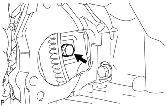
Install the 6 drive plate and torque converter setting bolts.
- Torque:
- 53 N*m { 535 kgf*cm, 39 ft.*lbf }
Note
-
First install the black-colored bolt, and then the remaining 5 silver colored bolts.
-
Turn the crankshaft to install the 6 drive plate and torque converter setting bolts.
-
-
INSTALL NO. 2 MANIFOLD STAY
-
INSTALL NO. 1 MANIFOLD STAY
-
CONNECT FLOOR SHIFT GEAR SHIFTING ROD SUB-ASSEMBLY
-
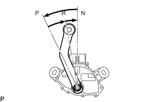
Turn the transmission control shaft lever of the park/neutral position switch counterclockwise until it stops, and then turn it clockwise 2 notches to set it to the N position.
-
Move the shift lever to N.
-
Connect the floor shift gear shifting rod sub-assembly to the transmission control shaft lever with the pin and a new clip.
-
-
INSTALL NO. 3 FRONT FLOOR HEAT INSULATOR
-
INSTALL STARTER ASSEMBLY
-
INSTALL EXHAUST PIPE
-
INSTALL PROPELLER SHAFT ASSEMBLY
-
INSTALL FRONT PROPELLER SHAFT ASSEMBLY
-
CONNECT CABLE TO NEGATIVE BATTERY TERMINAL
Note
When disconnecting the cable, some systems need to be initialized after the cable is reconnected Click here.
-
ADD AUTOMATIC TRANSMISSION FLUID
-
ADD TRANSFER OIL
-
ADD ENGINE COOLANT
-
INSPECT FOR AUTOMATIC TRANSMISSION FLUID LEAK
-
INSPECT FOR ENGINE COOLANT LEAK
-
INSPECT SHIFT LEVER POSITION
-
INSPECT FOR EXHAUST GAS LEAK
-
INSTALL FRONT FENDER APRON SEAL REAR RH
-
INSTALL FRONT FENDER APRON SEAL FRONT RH
-
INSTALL TRANSMISSION CASE COVER (w/ Cover)
-
INSTALL OIL PAN PROTECTOR ASSEMBLY
-
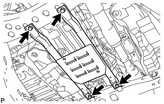
Install the oil pan protector with the 4 bolts.
- Torque:
- 50 N*m { 510 kgf*cm, 37 ft.*lbf }
-
-
INSTALL NO. 2 ENGINE UNDER COVER
-
INSTALL NO. 1 ENGINE UNDER COVER SUB-ASSEMBLY
-
INSTALL FRONT FENDER SPLASH SHIELD SUB-ASSEMBLY LH
-
INSTALL FRONT FENDER SPLASH SHIELD SUB-ASSEMBLY RH
-
INSTALL UPPER RADIATOR SUPPORT SEAL
-
RESET MEMORY
-
Perform the Reset Memory procedures (A/T initialization) Click here.
-