| DTC Code | DTC Name |
|---|---|
| P0500 | Vehicle Speed Sensor |
DESCRIPTION
The speed sensor detects the wheel speed and sends the appropriate signals to the skid control ECU. The skid control ECU converts these wheel speed signals into a pulse signal and outputs it to the TCM via the combination meter. The TCM determines the vehicle speed based on the frequency of this pulse signal.
| DTC Code | DTC Detection Condition
|
Trouble Area |
|---|---|---|
| P0500 |
|
|
MONITOR DESCRIPTION
The TCM assumes that the vehicle is being driven when the indicated vehicle speed is more than 9 km/h (5.59 mph). If there is no speed signal from the combination meter despite this condition being met, the TCM interprets this as a malfunction in the speed signal circuit. The TCM then illuminates the MIL and stores the DTC.
WIRING DIAGRAM
CAUTION / NOTICE / HINT
Perform registration and/or initialization when parts related to the automatic transmission are replaced (Click here).
After the repair, clear the DTCs and perform the following procedure to check that DTCs are not output.
-
Turn the engine switch on (IG) and wait for 3 seconds or more.*1
-
Drive the vehicle at 9 km/h (5.59 mph) or more for 5 seconds or more.*2
-
Turn the engine switch off.
-
Perform steps (*1) through (*2) again.
-
Check for DTCs again (Click here).
PROCEDURE
- Click here
CHECK OPERATION OF SPEEDOMETER
-
Drive the vehicle and check whether the operation of the speedometer in the combination meter is normal.
Tip:
-
The vehicle speed sensor is operating normally if the speedometer reading is normal.
-
If the speedometer does not operate, check it by following the procedure described in Speedometer Malfunction (Click here).
-
- OKClick here
- NG
GO TO MALFUNCTION IN SPEEDOMETER (Click here)
-
- Click here
READ VALUE USING GTS (VEHICLE SPEED)
-
Connect the GTS to the DLC3.
-
Turn the engine switch on (IG).
-
Turn the GTS on.
-
Enter the following menus: Powertrain / ECT / Data List / Vehicle Speed.
-
Drive the vehicle.
-
In accordance with the display on the GTS, read the Data List.
Table 2. ECT Tester Display Measurement Item/Range Normal Condition Diagnostic Note Vehicle Speed Vehicle speed/
Min.: 0 km/h (0 mph)
Max.: 255 km/h (158 mph)
Actual vehicle speed - OK Vehicle speed displayed on GTS and speedometer display are equal.
- OK
CHECK FOR INTERMITTENT PROBLEMS (Click here)
- NGClick here
-
- Click here
CHECK HARNESS AND CONNECTOR (COMBINATION METER ASSEMBLY - TCM)
-
Disconnect the E119 combination meter assembly connector.
-
Disconnect the A82 TCM connector.
-
Measure the resistance according to the value(s) in the table below.
Standard Resistance Tester Connection Condition Specified Condition E119-6 (+S) - A82-18 (SPD) Always Below 1 Ω E119-6 (+S) or A82-18 (SPD) - Body ground Always 10 kΩ or higher Tip:If the wire harness has a short, check the speed signal circuit in other systems related to the vehicle speed signal (e.g. SFI system, audio system, etc.).
- OKClick here
- NG
REPAIR OR REPLACE HARNESS OR CONNECTOR (OTHER SYSTEMS RELATED TO SPEED SIGNAL)
-
- Click here
CHECK COMBINATION METER ASSEMBLY (+S VOLTAGE)
-
Disconnect the combination meter connector.
-
Turn the engine switch on (IG).
-
Measure the voltage according to the value(s) in the table below.
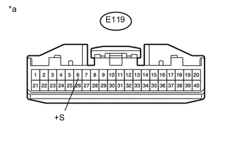
Standard Voltage Tester Connection Switch Condition Specified Condition E119-6 (+S) - Body ground Engine switch on (IG) 4.5 to 5.5 V Table 3. Text in Illustration *a Front view of wire harness connector
(to Combination Meter Assembly)
- OKClick here
- NG
REPLACE TCM (Click here)
-
- Click here
INSPECT COMBINATION METER ASSEMBLY (SPD SIGNAL OUTPUT WAVEFORM)
-
Remove the combination meter.
-
Connect the combination meter connector.
-
Move the shift lever to the neutral position.
-
Jack up the vehicle.
-
Turn the engine switch on (IG).
-
Measure the voltage according to the value(s) in the table below.
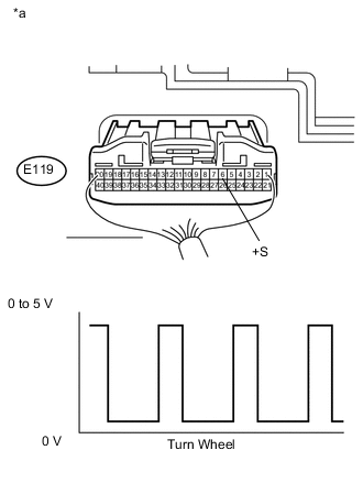
Standard Voltage Tester Connection Switch Condition Specified Condition E119-6 (+S) - Body ground Engine switch on (IG)
(Turn wheel slowly)
Voltage generated intermittently Table 4. Text in Illustration *a Component with harness connected
(Combination Meter Assembly)
Tip:The output voltage should fluctuate up and down, similarly to the diagram, when the wheel is turned slowly.
- OK
REPLACE TCM (Click here)
- NGClick here
-
- Click here
CHECK COMBINATION METER ASSEMBLY (SPD SIGNAL INPUT WAVEFORM)
-
Remove the combination meter.
-
Connect the combination meter connector.
-
Move the shift lever to the neutral position.
-
Jack up the vehicle.
-
Turn the engine switch on (IG).
-
Check the voltage between the body ground while the wheel is turned slowly.
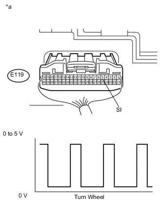
Standard Voltage Tester Connection Switch Condition Specified Condition E119-5 (SI) - Body ground Engine switch on (IG)
(Turn wheel slowly)
Voltage generated intermittently Table 5. Text in Illustration *a Component with harness connected
(Combination Meter Assembly)
Tip:The output voltage should fluctuate up and down, similarly to the diagram, when the wheel is turned slowly.
- OK
REPLACE COMBINATION METER ASSEMBLY (Click here)
- NGClick here
-
- Click here
CHECK HARNESS AND CONNECTOR (COMBINATION METER ASSEMBLY - SKID CONTROL ECU)
-
Disconnect the E119 combination meter connector.
-
Disconnect the A24 skid control ECU connector.
-
Measure the resistance according to the value(s) in the table below.
Standard Resistance Tester Connection Condition Specified Condition E119-5 (SI) - A24-12 (SP1) Always Below 1 Ω E119-5 (SI) or A24-12 (SP1) - Body ground Always 10 kΩ or higher
- OK
REPLACE SKID CONTROL ECU (MASTER CYLINDER SOLENOID) (Click here)
- NG
REPAIR OR REPLACE HARNESS OR CONNECTOR
-