AUTOMATIC TRANSMISSION SYSTEM TERMINALS OF ECU
-
TCM
Tech Tips
The standard voltage and resistance of each TCM terminal is shown in the table below.
In the table, first follow the information under "Condition". Look under "Terminal No. (Symbol)" for the terminals to be inspected. The standard voltage or resistance between the terminals is shown under "Specified Condition".
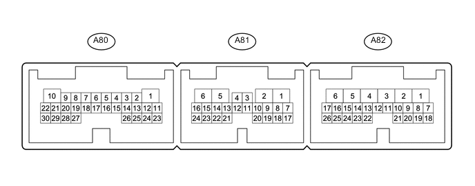
Use the illustration above as a reference for the TCM terminals.
Terminal No. (Symbol) Wiring Color Terminal Description Condition Specified Condition A80-1 (GND) - Body ground W-B - Body ground Ground Always Below 1 Ω A80-3 (SL2+) - A80-2 (SL2-) LG - R Shift solenoid valve SL2 signal 1st, 2nd, 3rd or 4th gear Pulse generation A80-5 (SLT+) - A80-4 (SLT-) B - LG Shift solenoid valve SLT signal Engine idling Pulse generation A80-7 (SLU+) - A80-6 (SLU-) R - L Shift solenoid valve SLU signal 5th, 6th, 7th or 8th gear
(Lock-up ON)
3rd, 4th, 5th, 6th, 7th or 8th gear
(Flex lock-up ON)
Pulse generation A80-9 (SL1+) - A80-8 (SL1-) R - B Shift solenoid valve SL1 signal 1st, 2nd, 3rd, 4th or 5th gear Pulse generation A80-10 (+B) - A80-1 (GND) B - W-B Power source of TCM Engine switch on (IG) 11 to 14 V A80-21 (IGSW) - A80-1 (GND) B - W-B Engine switch Engine switch on (IG) 11 to 14 V A80-23 (THO1) - A80-24 (E2) B - G No. 1 ATF temperature sensor signal ATF temperature 115°C (239°F) or more Below 1.5 V A80-26 (THOC) - A80-25 (ETH2) L - R No. 2 ATF temperature sensor signal ATF temperature 115°C (239°F) or more Below 1.5 V A80-28 (SC2) - A80-1 (GND) V - W-B Shift solenoid valve SC2 signal Shift lever in S: S1 (1st gear) selected 11 to 14 V A80-30 (SC1) - A80-1 (GND) W - W-B Shift solenoid valve SC1 signal All gears 11 to 14 V A81-1 (SP2B) - A80-1 (GND) B - W-B Power source for sensor (specific voltage) Engine switch on (IG) 11 to 14 V A81-2 (SP2O) - A80-1 (GND) G - W-B Transmission revolution sensor (SP2) signal Vehicle speed 20 km/h (12 mph) Pulse generation A81-4 (SL5+) - A81-3 (SL5-) W - R Shift solenoid valve SL5 signal 2nd or 8th gear Pulse generation A81-7 (NTB) - A80-1 (GND) P - W-B Power source for sensor (specific voltage) Engine switch on (IG) 11 to 14 V A81-8 (NTO) - A80-1 (GND) L - W-B Transmission revolution sensor (NT) signal Engine idling (shift lever in P or N) Pulse generation A81-14 (SL4+) - A81-5 (SL4-) G - V Shift solenoid valve SL4 signal 4th or 6th gear Pulse generation A81-16 (SL3+) - A81-6 (SL3-) L - B Shift solenoid valve SL3 signal 1st, 2nd, 4th, 5th, 6th or 8th gear Pulse generation A82-1 (CAN+) - A80-1 (GND) R - W-B CAN communication line Engine switch on (IG) Pulse generation A82-2 (CAN-) - A80-1 (GND) W - W-B CAN communication line Engine switch on (IG) Pulse generation A82-5 (R) - A80-1 (GND) L - W-B R shift position switch signal Engine switch on (IG) and shift lever in R 11 to 14 V Engine switch on (IG) and shift lever not in R Below 1 V A82-6 (C) - A80-1 (GND) P - W-B Shift position switch signal Engine switch on (IG) and shift lever in D, S, "+" or "-" 11 to 14 V Engine switch on (IG) and shift lever not in D, S, "+" or "-" Below 1 V A82-7 (EC) - Body ground W-B - Body ground Ground Always Below 1 Ω A82-16 (PA) - A80-1 (GND) GR - W-B Shift position switch signal Engine switch on (IG) and shift lever in P or N 11 to 14 V Engine switch on (IG) and shift lever not in P or N Below 1 V A82-17 (B) - A80-1 (GND) R - W-B Shift position switch signal Engine switch on (IG) and shift lever in R, N, D, S, "+" or "-" 11 to 14 V Engine switch on (IG) and shift lever not in R, N, D, S, "+" or "-" Below 1 V A82-18 (SPD) - A80-1 (GND) L - W-B Vehicle speed signal from combination meter assembly signal Vehicle driving Pulse generation A82-24 (L4) - A80-1 (GND) R - W-B L4 position signal Engine switch on (IG) and transfer in L4 Below 1 V Engine switch on (IG) and transfer not in L4 11 to 14 V A82-26 (A) - A80-1 (GND) W - W-B Shift position switch signal Engine switch on (IG) and shift lever in P or R 11 to 14 V Engine switch on (IG) and shift lever not in P or R Below 1 V -
ECM
Tech Tips
The standard voltage of each ECM terminal is shown in the table below.
In the table, first follow the information under "Condition". Look under "Terminal No. (Symbol)" for the terminals to be inspected. The standard voltage between the terminals is shown under "Specified Condition".
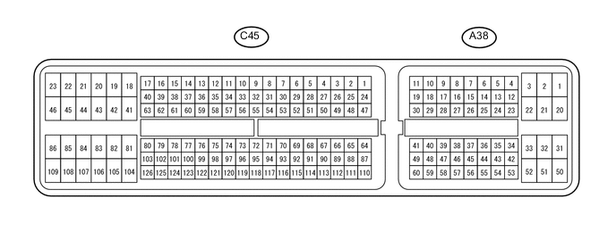
Use the illustration above as a reference for the ECM terminals.
Terminal No. (Symbol) Wiring Color Terminal Description Condition Specified Condition A38-2 (+B) - C45-81 (E1) B - W-B Power source of ECM Engine switch on (IG) 11 to 14 V A38-3 (+B2) - C45-81 (E1) B - W-B Power source of ECM Engine switch on (IG) 11 to 14 V A38-12 (SNWI) - C45-81 (E1) P - W-B ECT 2nd switch (integration control and panel assembly) signal Engine switch on (IG) and ECT 2nd switch off 11 to 14 V Engine switch on (IG) and ECT 2nd switch on Below 1 V A38-13 (PWR) - C45-81 (E1) GR - W-B PWR switch (integration control and panel assembly) signal*1 Engine switch on (IG) and PWR switch off 11 to 14 V Engine switch on (IG) and PWR switch on Below 1 V A38-27 (S) - C45-81 (E1) W - W-B S shift position switch signal Engine switch on (IG) and shift lever in S 11 to 14 V Engine switch on (IG) and shift lever not in S Below 1 V A38-34 (PWMS) - C45-81 (E1) GR - W-B SPORT S/S+ switch (integration control and panel assembly) signal*2 Engine switch on (IG) and SPORT S/S+ switch off 11 to 14 V Engine switch on (IG) and SPORT S/S+ switch on Below 1 V A38-39 (SFTU) - C45-81 (E1) V - W-B Up-shift shift position switch signal Engine switch on (IG) and shift lever in S 11 to 14 V Engine switch on (IG) and shift lever held in "+" Below 1 V A38-47 (SFTD) - C45-81 (E1) L - W-B Down-shift position switch signal Engine switch on (IG) and shift lever in S 11 to 14 V Engine switch on (IG) and shift lever held in "-" Below 1 V A38-49 (SPCN) - C45-81 (E1) L - W-B NORM switch (integration control and panel assembly) signal*2 Engine switch on (IG) and NORM switch off 11 to 14 V Engine switch on (IG) and NORM switch on Below 1 V
-
*1: w/o Active Height Control Suspension
-
*2: w/ Active Height Control Suspension
-