AUTOMATIC TRANSMISSION SYSTEM, Diagnostic DTC:P2757
| DTC Code | DTC Name |
|---|---|
| P2757 | Torque Converter Clutch Pressure Control Solenoid Control Circuit Performance or Stuck OFF |
DESCRIPTION
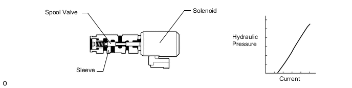
The TCM controls the lock-up solenoid, and performs lock-up and flex lock-up control.
The TCM compares the engagement condition of the lock-up clutch with the lock-up schedule in the TCM memory to detect shift solenoid valve SLU, transmission valve body assembly and torque converter mechanical problems.
| DTC No. | DTC Detection Condition
|
Trouble Area |
|---|---|---|
| P2757 |
|
|
|
|
MONITOR DESCRIPTION
Torque converter lock-up is controlled by the TCM based on the transmission revolution sensor (NT), engine speed, engine load, engine coolant temperature, vehicle speed, transmission fluid temperature and gear selection. The TCM determines the lock-up status of the torque converter by comparing the engine speed (NE) to the input turbine speed (NT). The TCM calculates the actual transmission gear by comparing the input turbine speed (NT) to the output shaft speed (SP2). When conditions are appropriate, the TCM requests "lock-up" by applying control voltage to the shift solenoid valve SLU. When the shift solenoid valve SLU is turned on, it applies pressure to the lock-up relay valve and locks the torque converter assembly.
If the TCM detects no lock-up after lock-up has been requested or if it detects lock-up when it is not requested, the TCM interprets this as a malfunction of the shift solenoid valve SLU, and stores this DTC.
Tech Tips
Example:
When any of the following is met, the system judges it as a malfunction.
-
There is a difference in speed between the input side (engine speed) and output side (input turbine speed) of the torque converter when the TCM commands lock-up. (Engine speed is at least 100 rpm more than input turbine speed.)
-
There is no difference in speed between the input side (engine speed) and output side (input turbine speed) of the torque converter when the TCM commands lock-up off. (The difference between engine speed and input turbine speed is less than 30 rpm.)
CAUTION / NOTICE / HINT
Note
Perform registration and/or initialization when parts related to the automatic transmission are replaced Click here.
Tech Tips
-
(Only for vehicles with an AE80F automatic transmission.)
-
When an engine stall occurs, control that cuts the clutch oil pressure inside the automatic transmission (engine stall avoidance control) may be performed. After the engine is restarted, the vehicle will not creep, even if the shift lever is in D, S or R.
During control operation, "Check Transmission System" is displayed on the multi-information display.
-
With the brake pedal released, slowly depress the accelerator pedal until the vehicle begins to move. This engages the clutch and makes it possible for the vehicle to start off.
-
Afterwards, briefly drive the vehicle at a constant speed with the engine RPM between 1000 and 3000 to cancel the engine stall avoidance control.
In addition, it is possible to cancel the control by using the GTS to clear the ECT DTCs.
-
After the vehicle starts off, if the vehicle is stopped before the above requirements are met, the engine stall avoidance control will not cancel and the vehicle will not creep again.
-
After performing repair, clear the DTCs and perform the following procedure to check that DTCs are not output.
-
Perform the Lock-up Function in Road Test Click here.*1
-
Turn the engine switch off.
-
Perform step (*1) again.
-
Check for DTCs again Click here.
PROCEDURE
-
CHECK DTC OUTPUT (IN ADDITION TO DTC P2757)
-
Connect the GTS to the DLC3.
-
Turn the engine switch on (IG).
-
Turn the GTS on.
-
Enter the following menus: Powertrain / ECT / Trouble Codes.
-
Read the DTCs using the GTS.
Result Result Proceed to Only DTC P2757 is output A DTC P2757 and other DTCs are output B Tech Tips
If any other codes besides P2757 are output, perform troubleshooting for those DTCs first.
B 
GO TO DTC CHART Click here
A 
-
-
INSPECT SHIFT SOLENOID VALVE SLU
-
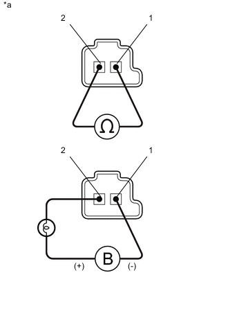
Text in Illustration *1 Shift Solenoid Valves SLU Remove the shift solenoid valve SLU Click here.
-
Measure the resistance according to the value(s) in the table below.
Standard Resistance Tester Connection Condition Specified Condition Terminal 1 of the shift solenoid valve SLU - Terminal 2 20°C (68°F) 5.0 to 5.6 Ω -
Apply 12 V battery voltage to the shift solenoid valve and check that the valve moves and makes an operating noise.
OK Measurement Condition Specified Condition
-
Battery positive (+) with a 21 W bulb → Terminal 2
-
Battery negative (-) → Terminal 1
Valve moves and makes an operating noise -
NG
REPLACE SHIFT SOLENOID VALVE SLU Click here
OK
-
-
INSPECT TRANSMISSION VALVE BODY ASSEMBLY
-
Check the transmission valve body assembly Click here.
OK There is no foreign matter on each valve and they operate smoothly.
NG
REPAIR OR REPLACE TRANSMISSION VALVE BODY ASSEMBLY Click here
OK
-
-
INSPECT TORQUE CONVERTER ASSEMBLY
-
Check the torque converter assembly Click here.
OK The torque converter operates normally.
OK
REPAIR OR REPLACE AUTOMATIC TRANSMISSION ASSEMBLY Click here
NG
REPLACE TORQUE CONVERTER ASSEMBLY Click here
-