SHIFT LEVER INSPECTION
PROCEDURE
-
INSPECT SHIFT LOCK SOLENOID
-
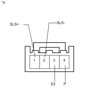
Text in Illustration *a Component with harness connected
(Shift Lock Solenoid)
Disconnect the shift lock solenoid connector from the shift lock control ECU.
-
Measure the resistance according to the values in the table below.
Standard Resistance Tester Connection Condition Specified Condition 1 (SLS+) - 2 (SLS-) Always 101 to 123 Ω 3 (E2) - 4 (P) Shift lever in P 10 kΩ or higher Shift lever not in P Below 1 Ω -
Apply 12 V battery voltage to the shift lock solenoid and check that the valve moves and makes an operating noise.
OK Measurement Condition Specified Condition
-
Battery positive (+) → Terminal 1 (SLS+)
-
Battery negative (-) → Terminal 2 (SLS-)
Solenoid moves and makes an operating noise If the result is not as specified, replace the shift lever assembly.
-
-
-
INSPECT TRANSMISSION CONTROL SWITCH
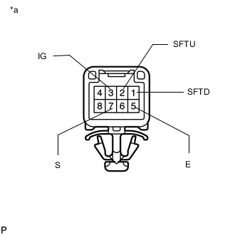
Text in Illustration *a Component without harness connected
(Transmission Control Switch)
-
Measure the resistance according to the value(s) in the table below.
Standard Resistance Tester Connection Condition Specified Condition 3 (IG) - 7 (S) Shift lever in S, "+" or "-" Below 1 Ω 2 (SFTU) - 5 (E) Shift lever held in "+" (Up-shift) 1 (SFTD) - 5 (E) Shift lever held in "-" (Down-shift) 3 (IG) - 7 (S) Shift lever not in S, "+" or "-" 10 kΩ or higher 2 (SFTU) - 5 (E) Shift lever not held in "+" (Up-shift) 1 (SFTD) - 5 (E) Shift lever not held in "-" (Down-shift) If the result is not as specified, replace the transmission floor shift assembly.
-