AUTOMATIC TRANSMISSION ASSEMBLY(for 1VD-FTV) INSTALLATION
CAUTION / NOTICE / HINT
CAUTION:
The automatic transmission assembly is very heavy. Be sure to follow the procedure described in the repair manual, or the transmission jack may suddenly drop.
PROCEDURE
-
INSTALL TORQUE CONVERTER CLUTCH ASSEMBLY
-
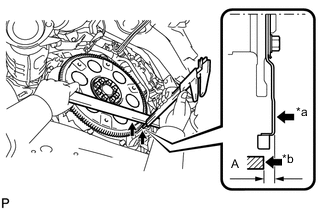
Text in Illustration *a Drive Plate Surface *b Engine Assembly Surface Using a vernier caliper and straightedge, measure the dimension (A) between the automatic transmission assembly contact surface of the engine assembly (*b) and the torque converter assembly contact surface of the drive plate (*a).
-
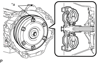
Text in Illustration *a Matchmark Align the matchmark on the automatic transmission case sub-assembly with the one on the torque converter assembly and engage the splines of the input shaft with the turbine runner splines.
Note
Install the torque converter assembly to the input shaft while keeping it horizontal.
-
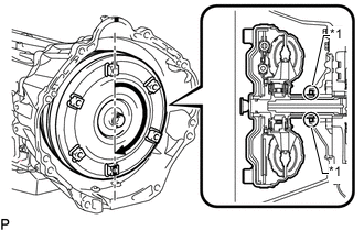
Text in Illustration *1 Front Oil Pump Oil Seal Rotate the torque converter assembly approximately 180° and engage the splines of the stator shaft with the stator assembly.
Note
-
Do not damage the front oil pump oil seal.
-
Install the torque converter assembly to the input shaft while keeping it horizontal.
-
-
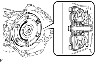
Text in Illustration *1 Front Oil Pump Oil Seal Rotate the torque converter assembly approximately 180° again, align the matchmark on the torque converter assembly with the one on the automatic transmission case sub-assembly and insert the key of the torque converter assembly into the groove of the oil pump drive gear.
Note
-
Do not push the torque converter assembly excessively when rotating it.
-
Do not damage the front oil pump oil seal.
-
Install the torque converter assembly to the input shaft while keeping it horizontal.
-
-
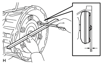
Using a vernier caliper and straightedge, measure the dimension (B) shown in the illustration and check that the dimension (B) is more than the dimension (A), which was measured in the previous step.
Standard distance B = A + 1.00 mm (0.0394 in.) or more Note
-
Make sure to deduct the thickness of the straightedge.
-
If the automatic transmission assembly is installed to the engine assembly with the torque converter assembly not sufficiently inserted, the torque converter assembly may be damaged.
-
-
-
INSTALL TRANSFER ASSEMBLY
-
REMOVE LOWER TRANSFER CASE PROTECTOR
-
Install the lower transfer case protector with the 7 bolts and attach the clamp.
- Torque:
- 14 N*m { 143 kgf*cm, 10 ft.*lbf }
-
-
INSTALL AUTOMATIC TRANSMISSION ASSEMBLY
-
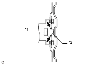
Text in Illustration *1 Crankshaft *2 Torque Converter Assembly Centerpiece 
Clutch Spline Grease Apply clutch spline grease to the surface of the crankshaft that contacts the torque converter assembly centerpiece.
Clutch spline grease Toyota Genuine Clutch Spline Grease or equivalent Maximum grease amount Approximately 1 g (0.0353 oz.) -
Confirm that the 2 knock pins are installed on the engine assembly and are not damaged.
-
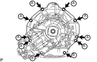
While keeping the engine assembly and automatic transmission assembly horizontal, align the 2 knock pins with the holes in the automatic transmission assembly and install the 10 bolts.
- Torque:
- for 17 mm head bolt A
- 71 N*m { 724 kgf*cm, 52 ft.*lbf }
- for 14 mm head bolt B
- 37 N*m { 377 kgf*cm, 27 ft.*lbf }
Note
-
Do not use excessive force when installing the automatic transmission assembly.
-
Check that the torque converter assembly rotates.
-
Make sure that the wire harness or other similar items are not pinched between the contact surfaces.
-
Make sure that the cooling fan and fan shroud do not contact the engine assembly when tilting the automatic transmission assembly.
-
-
INSTALL TRANSMISSION HOUSING COVER
-
Install the transmission housing cover with the 3 bolts.
- Torque:
- 12 N*m { 122 kgf*cm, 9 ft.*lbf }
-
-
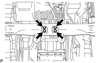
INSTALL OIL PAN COVER
-
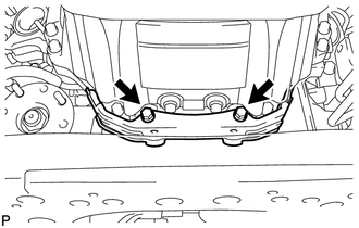
Install the oil pan cover with the 2 bolts.
- Torque:
- 21 N*m { 214 kgf*cm, 15 ft.*lbf }
-
-
CONNECT WIRE HARNESS AND CONNECTOR
-
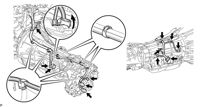
Connect the park/neutral position switch connector, 2 transmission wire connectors, 2 speed sensor connectors and 2 or 3 transfer control side connectors.
Tech Tips
Push up the lever until the claw of the transmission wire connector makes a connection sound.
-
Connect the 8 harness clamps.
-
Connect the wire harness with the 2 bolts.
- Torque:
- 8.0 N*m { 82 kgf*cm, 71 in.*lbf }
-
Tilt up the automatic transmission.
-
-
CONNECT BREATHER PLUG HOSE
-
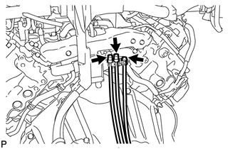
Connect the 3 breather plug hoses to the wire harness.
-
-
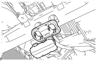
INSTALL REAR NO. 1 ENGINE MOUNTING INSULATOR
-
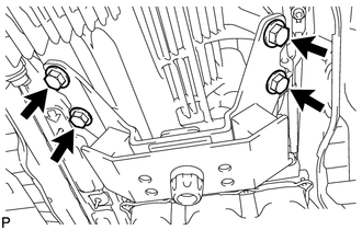
Install the rear No. 1 engine mounting insulator to the automatic transmission assembly with the 4 bolts.
- Torque:
- 59 N*m { 602 kgf*cm, 44 ft.*lbf }
-
-
INSTALL NO. 2 FRAME CROSSMEMBER SUB-ASSEMBLY
-
Install the No. 2 frame crossmember sub-assembly to the rear No. 1 engine mounting insulator with the 4 bolts.
- Torque:
- 37 N*m { 377 kgf*cm, 27 ft.*lbf }
-
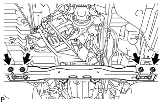
Install the No. 2 frame crossmember sub-assembly to the frame with the 4 bolts and 4 nuts.
- Torque:
- 110 N*m { 1122 kgf*cm, 81 ft.*lbf }
-
Install the engine mounting hole cover.
-
-
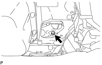
CONNECT GROUND CABLE
-
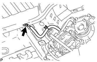
Connect the ground cable with the bolt.
- Torque:
- 8.4 N*m { 86 kgf*cm, 74 in.*lbf }
-
-
CONNECT OIL COOLER TUBE
-
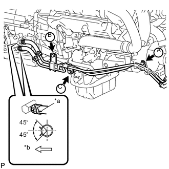
Text in Illustration *a Paint Mark *b RH Side Connect the 2 transmission oil cooler hoses as shown in the illustration.
Note
-
Make sure the pinching portion of each clip is facing the direction shown in the illustration.
-
Make sure the paint mark of each hose is facing outward.
-
-
Temporarily install the oil cooler tube to the engine with the bolts A and B. Install the bolt C and tighten it to the specified torque. Then tighten the bolts A and B to the specified torque.
- Torque:
- 14 N*m { 143 kgf*cm, 10 ft.*lbf }
-
-
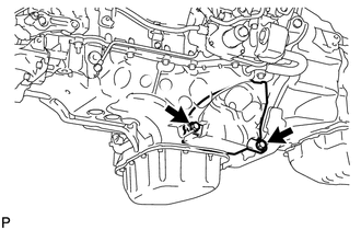
INSTALL DRIVE PLATE AND TORQUE CONVERTER SETTING BOLT
-
Turn the crankshaft to gain access to the installation locations of the 6 drive plate and torque converter setting bolts and install each bolt while holding the crankshaft pulley set bolt with a wrench.
- Torque:
- 53 N*m { 540 kgf*cm, 39 ft.*lbf }
Note
First install the black colored bolt and then install the remaining 5 bolts.
-
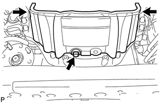
Install the oil pan insulator with the 2 bolts.
- Torque:
- 21 N*m { 214 kgf*cm, 15 ft.*lbf }
-
-
INSTALL EXHAUST PIPE (w/ DPF)
-
INSTALL EXHAUST PIPE (w/o DPF)
-
INSTALL PROPELLER SHAFT ASSEMBLY
-
INSTALL FRONT PROPELLER SHAFT ASSEMBLY
-
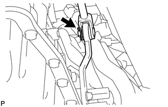
CONNECT FLOOR SHIFT GEAR SHIFTING ROD SUB-ASSEMBLY
-
Connect the gear shifting rod to the transmission control shaft lever RH with the pin and a new clip.
-
-
CONNECT CABLE TO NEGATIVE BATTERY TERMINAL
Note
When disconnecting the cable, some systems need to be initialized after the cable is reconnected Click here.
-
ADD AUTOMATIC TRANSMISSION FLUID
-
INSPECT SHIFT LEVER POSITION
-
When moving the shift lever from P to R with the ignition switch ON and the brake pedal depressed, make sure that it moves smoothly and correctly into position.
-
Check that the shift lever does not stop when moving the shift lever from R to P, and check that the shift lever does not stick when moving the shift lever from D to S.
-
Start the engine and make sure that the vehicle moves forward after moving the shift lever from N to D and moves rearward after moving the shift lever to R.
If there are problems during the above inspections, perform the adjustment using the following procedures.
-
Move the shift lever to N
-
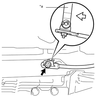
Text in Illustration *a Lever Nut 
Push Loosen the nut of the floor shift gear shifting rod. Then, with the lever of the floor shift assembly lightly pushed towards the rear of the vehicle, tighten the nut.
- Torque:
- 13 N*m { 130 kgf*cm, 9 ft.*lbf }
-
-
-
INSPECT FOR EXHAUST GAS LEAK
-
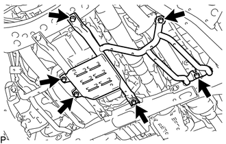
INSTALL OIL PAN PROTECTOR ASSEMBLY RH (w/ DPF)
-
Install the oil pan protector assembly RH with the 4 bolts.
- Torque:
- 50 N*m { 510 kgf*cm, 37 ft.*lbf }
-
-
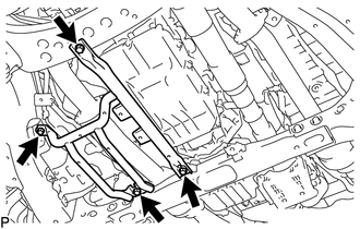
INSTALL OIL PAN PROTECTOR ASSEMBLY LH (w/ DPF)
-
Install the oil pan protector assembly LH with the 6 bolts.
- Torque:
- 50 N*m { 510 kgf*cm, 37 ft.*lbf }
-
-
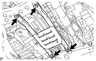
INSTALL OIL PAN PROTECTOR ASSEMBLY (w/o DPF)
-
Install the oil pan protector assembly with the 4 bolts.
- Torque:
- 50 N*m { 510 kgf*cm, 37 ft.*lbf }
-
-
INSTALL FRONT FENDER APRON SEAL REAR RH
-
INSTALL FRONT FENDER APRON SEAL FRONT RH
-
INSTALL NO. 2 ENGINE UNDER COVER
-
INSTALL NO. 1 ENGINE UNDER COVER SUB-ASSEMBLY
-
INSTALL FRONT FENDER SPLASH SHIELD SUB-ASSEMBLY LH
-
INSTALL FRONT FENDER SPLASH SHIELD SUB-ASSEMBLY RH
-
RESET MEMORY
w/ DPF Click here
w/o DPF Click here