SHIFT LEVER(w/o Entry and Start System) REASSEMBLY
PROCEDURE
-
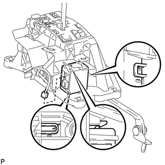
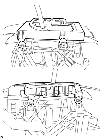
INSTALL SHIFT LOCK CONTROL ECU
-
Attach the 3 claws to install the ECU to the floor shift.
-
Connect the shift lock solenoid connector.
-
-
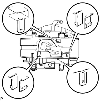
INSTALL LOWER POSITION INDICATOR HOUSING
-
Attach the 6 claws to install the housing.
-
-
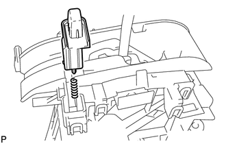
INSTALL SHIFT LOCK RELEASE BUTTON
-
Attach the 2 claws to install the spring and button.
-
-
INSTALL POSITION INDICATOR SLIDE COVER AND NO. 2 POSITION INDICATOR SLIDE COVER
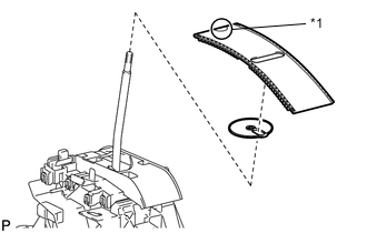
*1 Mark
-
Install the No. 2 position indicator slide cover to the position indicator slide cover.
-
Install the position indicator slide cover together with the No. 2 position indicator slide cover.
Tech Tips
Install the position indicator slide cover so that its mark faces the vehicle front.
-
-
INSTALL POSITION INDICATOR LENS
-
Attach the 4 claws to install the position indicator lens.
-
-
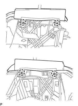
INSTALL POSITION INDICATOR HOUSING ASSEMBLY
-
Attach the 4 claws to install the position indicator housing.
-
-
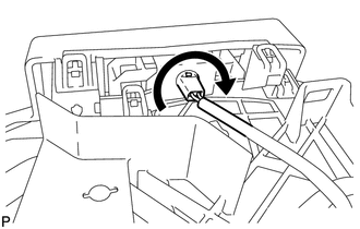
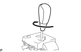
INSTALL INDICATOR LIGHT WIRE SUB-ASSEMBLY
-
Align the wire with the key part of the lower position indicator housing, and install the wire. Then rotate the wire clockwise until it locks.
-
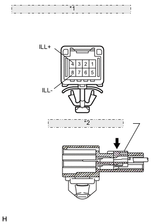
*1 Component without harness connected: (Transmission Control Switch) *2 Connector Housing Retainer Securely connect the 2 wire terminals to terminal 4 (ILL+) and 8 (ILL-) of the transmission control switch connector. Then push the connector housing retainer to lock it.
-
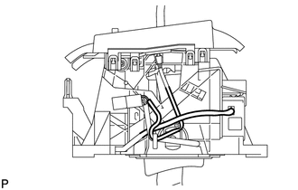
Check the shift lock solenoid and indicator light wire harness as shown in the illustration.
-
-
INSTALL SHIFT LEVER KNOB SUB-ASSEMBLY
- Torque:
- 3 N*m { 31 kgf*cm, 51 kgf*cm, 27 in.*lbf, 44 in.*lbf }