AUTOMATIC TRANSMISSION SYSTEM(for 1VD-FTV) Pattern Select Switch Power Mode Circuit
DESCRIPTION
The ECM memory contains the programs for the normal and power shift patterns and lock-up pattern.
By following the programs corresponding to the signals from the PWR switch, the park/neutral position switch and other various sensors, the ECM switches the solenoid valves on and off, and controls the transmission gear change and the lock-up clutch operation.
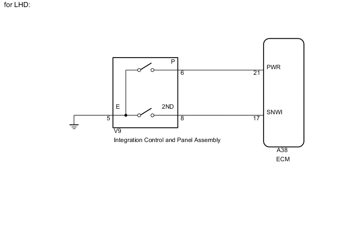
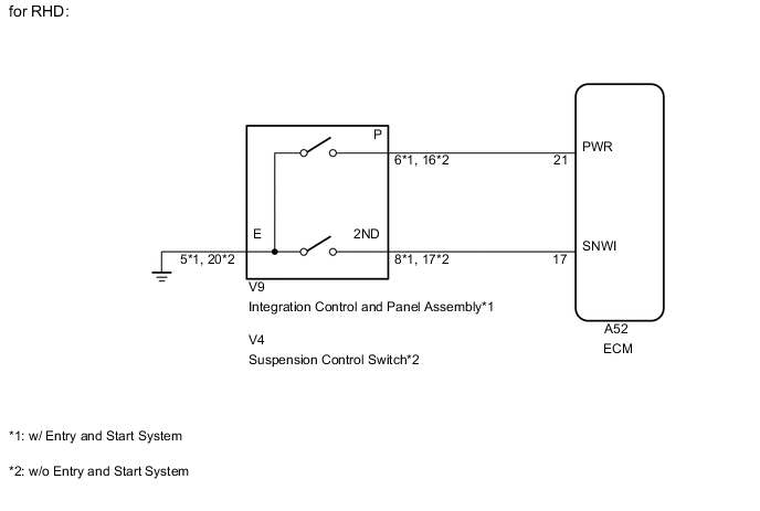
WIRING DIAGRAM
CAUTION / NOTICE / HINT
When the PWR switch is pushed, switch contact is made and power mode is selected. To cancel power mode, push the PWR switch once again.
PROCEDURE
-
INSPECT PWR SWITCH
-
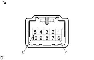
Text in Illustration *a Component without harness connected
(Integration Control and Panel Assembly)
w/ Entry and Start System:
Remove the integration control and panel assembly Click here.
-
Measure the resistance according to the value(s) in the table below.
Standard Resistance Tester Connection Switch Condition Specified Condition 6 (P) - 5 (E) PWR switch on Below 1 Ω 6 (P) - 5 (E) PWR switch off 10 kΩ or higher -
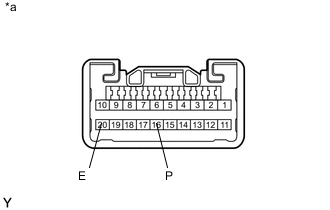
Text in Illustration *a Component without harness connected
(Suspension Control Switch)
w/o Entry and Start System:
Remove the suspension control switch Click here.
-
Measure the resistance according to the value(s) in the table below.
Standard Resistance Tester Connection Switch Condition Specified Condition 16 (P) - 20 (E) PWR switch on Below 1 Ω 16 (P) - 20 (E) PWR switch off 10 kΩ or higher Result Result Proceed to OK A NG (w/ Entry and Start System) B NG (w/o Entry and Start System) C
B 
REPLACE INTEGRATION CONTROL AND PANEL ASSEMBLY Click here
C
REPLACE SUSPENSION CONTROL SWITCH Click here
A 
-
-
CHECK HARNESS AND CONNECTOR (PWR SWITCH - BODY GROUND)
-
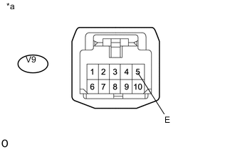
Text in Illustration *a Front view of wire harness connector
(to Integration Control and Panel Assembly)
w/ Entry and Start System:
Disconnect the integration control and panel assembly connector.
-
Measure the resistance according to the value(s) in the table below.
Standard Resistance Tester Connection Condition Specified Condition V9-5 (E) - Body ground Always Below 1 Ω -
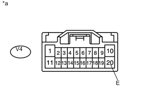
Text in Illustration *a Front view of wire harness connector
(to Suspension Control Switch)
w/o Entry and Start System:
Disconnect the suspension control switch connector.
-
Measure the resistance according to the value(s) in the table below.
Standard Resistance Tester Connection Condition Specified Condition V4-20 (E) - Body ground Always Below 1 Ω
NG
REPAIR OR REPLACE HARNESS OR CONNECTOR
OK
-
-
CHECK HARNESS AND CONNECTOR (PWR SWITCH - ECM)
-
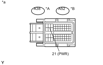
Text in Illustration A for LHD B for RHD *a Front view of wire harness connector
(to ECM)
Disconnect the ECM connector.
-
Measure the resistance according to the value(s) in the table below.
Standard Resistance for LHD Tester Connection Switch Condition Specified Condition A38-21 (PWR) - Body ground PWR switch on Below 1 Ω A38-21 (PWR) - Body ground PWR switch off 10 kΩ or higher for RHD Tester Connection Switch Condition Specified Condition A52-21 (PWR) - Body ground PWR switch on Below 1 Ω A52-21 (PWR) - Body ground PWR switch off 10 kΩ or higher
OK
PROCEED TO NEXT SUSPECTED AREA SHOWN IN PROBLEM SYMPTOMS TABLE Click here
NG
REPAIR OR REPLACE HARNESS OR CONNECTOR
-