AUTOMATIC TRANSMISSION SYSTEM(for 3UR-FE), Diagnostic DTC:P0982, P0983

| DTC Code | DTC Name |
|---|---|
| P0982 | Shift Solenoid "D" Control Circuit Low (Shift Solenoid Valve S4) |
| P0983 | Shift Solenoid "D" Control Circuit High (Shift Solenoid Valve S4) |
DESCRIPTION
Shifting from 1st to 6th is performed in combination with ON and OFF operation of the shift solenoid valves SL1, SL2, S1, S2, S3, S4 and SR, which are controlled by the ECM. If an open or short circuit occurs in any of the shift solenoid valves, the ECM controls the remaining normal shift solenoid valves to allow the vehicle to be operated safely. Also, the ECM stops sending the current to the open or short circuited solenoid Click here.
| DTC Code | DTC Detection Condition | Trouble Area |
|---|---|---|
| P0982 | ECM detects short in solenoid valve S4 circuit 2 times when solenoid valve S4 is operated (1 trip detection logic). |
|
| P0983 | ECM detects open in solenoid valve S4 circuit 2 times when solenoid valve S4 is not operated (1 trip detection logic). |
|
MONITOR DESCRIPTION
These DTCs indicate an open or short in the shift solenoid valve S4 circuit. When there is an open or short circuit in any shift solenoid valve circuit, the ECM detects the problem, illuminates the MIL and stores the DTC. When the shift solenoid valve S4 is ON, if its resistance is 8 Ω or less, the ECM determines there is a short in the shift solenoid valve S4 circuit.
When the shift solenoid valve S4 is OFF, if its resistance is 100 kΩ or more, the ECM determines there is an open in the shift solenoid valve S4 circuit Click here.
WIRING DIAGRAM
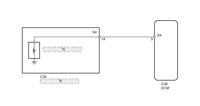
| *a | Shift Solenoid Valve S4 |
| *b | No. 1 Transmission Wire |
CAUTION / NOTICE / HINT
Tech Tips
Shift solenoid valve S4 is turned ON/OFF normally when the shift lever is in D.
| ECM gear shift command | 1st | 2nd | 3rd | 4th | 5th | 6th |
| Shift solenoid valve S4 | OFF | OFF | OFF | OFF | ON | ON |
PROCEDURE
-
INSPECT NO. 1 TRANSMISSION WIRE (SHIFT SOLENOID VALVE S4)
-
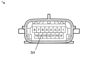
Text in Illustration *a Component without harness connected
(No. 1 Transmission Wire)
Disconnect the No. 1 transmission wire connector.
-
Measure the resistance according to the value(s) in the table below.
Standard Resistance Tester Connection Condition Specified Condition 14 (S4) - Body ground 20°C (68°F) 11 to 15 Ω
NG 
INSPECT SHIFT SOLENOID VALVE S4 Click here
OK 
-
-
CHECK HARNESS AND CONNECTOR (NO. 1 TRANSMISSION WIRE - ECM)
-
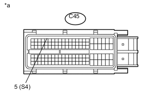
Text in Illustration *a Front view of wire harness connector
(to ECM)
Disconnect the ECM connector.
-
Measure the resistance according to the value(s) in the table below.
Standard Resistance Tester Connection Condition Specified Condition C45-5 (S4) - Body ground 20°C (68°F) 11 to 15 Ω
OK 
REPLACE ECM Click here
NG
REPAIR OR REPLACE HARNESS OR CONNECTOR
-
-
INSPECT SHIFT SOLENOID VALVE S4
-
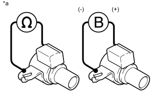
Text in Illustration *a Component without harness connected
(Shift Solenoid Valve S4)
Remove the shift solenoid valve S4.
-
Measure the resistance according to the value(s) in the table below.
Standard Resistance Tester Connection Condition Specified Condition Shift solenoid valve S4 connector terminal - Shift solenoid valve S4 body 20°C (68°F) 11 to 15 Ω -
Apply 12 V battery voltage to the shift solenoid valve and check that the valve moves and makes an operating noise.
OK Measurement Condition Specified Condition
-
Battery positive (+) → Shift solenoid valve S4 connector
-
Battery negative (-) → Shift solenoid valve S4 body
Valve moves and makes an operating noise -
OK
REPAIR OR REPLACE NO. 1 TRANSMISSION WIRE Click here
NG
REPLACE SHIFT SOLENOID VALVE S4 Click here
-