AUTOMATIC TRANSMISSION SYSTEM(for 1UR-FE), Diagnostic DTC:P2772

| DTC Code | DTC Name |
|---|---|
| P2772 | Four Wheel Drive (4WD) Low Switch Circuit Range / Performance |
DESCRIPTION
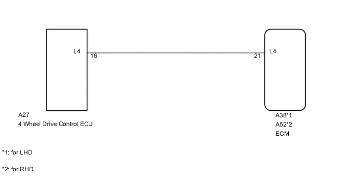
The ECM detects the signal from the transfer L4 position switch.
This DTC indicates that the transfer L4 position switch remains on.
| DTC Code | DTC Detection Condition | Trouble Area |
|---|---|---|
| P2772 | The transfer L4 position switch remains on while the vehicle is running under the following conditions for 1.8 sec. or more (1 trip detection logic). (a) The output shaft speed is between 1000 and 3000 rpm. (b) The transfer position switch is in H4. |
|
MONITOR DESCRIPTION
The ECM monitors the transfer-case L4 position switch to determine when the transfer-case L4 gears are engaged. If the L4 switch indicates that the transfer-case L4 gears remain engaged under the following conditions, the ECM will conclude that there is a malfunction of the L4 position switch, illuminate the MIL and store the DTC:
-
The transfer-case shifter is in the "H4" position.
-
The transfer-case output shaft rpm is between 1000 and 3000 rpm.
-
The specified time period has elapsed.
WIRING DIAGRAM
PROCEDURE
-
CHECK HARNESS AND CONNECTOR (4 WHEEL DRIVE CONTROL ECU - BODY GROUND)
-
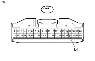
Text in Illustration *a Front view of wire harness connector
(to 4 Wheel Drive Control ECU)
Disconnect the 4 wheel drive control ECU connector.
-
Measure the resistance according to the value(s) in the table below.
Standard Resistance Tester Connection Condition Specified Condition A27-16 (L4) - Body ground Always 10 kΩ or higher
OK 
GO TO TRANSFER SYSTEM INSPECTION Click here
NG 
-
-
CHECK HARNESS AND CONNECTOR (4 WHEEL DRIVE CONTROL ECU - ECM)
-
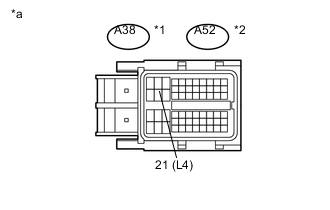
Text in Illustration *1 for LHD *2 for RHD *a Front view of wire harness connector
(to ECM)
Disconnect the ECM connector.
-
Disconnect the A27 4 wheel drive control ECU connector.
-
Measure the resistance according to the value(s) in the table below.
Standard Resistance for LHD Tester Connection Condition Specified Condition A38-21 (L4) - Body ground Always 10 kΩ or higher for RHD Tester Connection Condition Specified Condition A52-21 (L4) - Body ground Always 10 kΩ or higher
OK
REPLACE ECM Click here
NG
REPAIR OR REPLACE HARNESS OR CONNECTOR
-