AUTOMATIC TRANSMISSION UNIT DISASSEMBLY

PROCEDURE
-
REMOVE TRANSMISSION CONTROL SHAFT LEVER RH
-
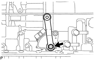
Remove the nut, spring washer and control shaft lever RH.
-
-
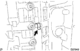
REMOVE PARK/NEUTRAL POSITION SWITCH ASSEMBLY
-
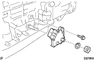
Using a screwdriver, bend the tabs of the lock washer.
-
Remove the nut, lock washer and bolt.
-
Remove the park/neutral position switch.
Tech Tips
Make sure that the manual valve lever shaft has not been rotated prior to installing the park/neutral position switch as the detent spring may become detached from the manual valve lever shaft.
-
-
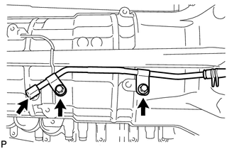
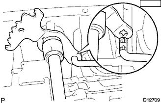
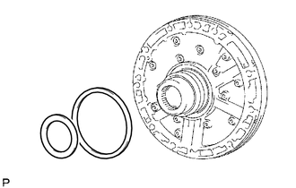
REMOVE OIL COOLER TUBE UNION
-
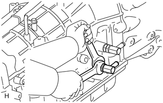
Remove the 2 oil cooler tube unions.
-
Remove the 2 O-rings from the oil cooler tube unions.
-
-
REMOVE SPEED SENSOR
-
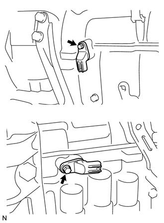
Remove the 2 bolts and 2 speed sensors.
-
Remove the 2 O-rings from the sensors.
-
-
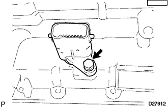
REMOVE AUTOMATIC TRANSMISSION BREATHER TUBE
-
Remove the 2 bolts.
-
Remove the breather tube.
-
Remove the O-ring from the tube.
-
-
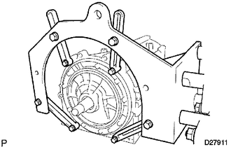
REMOVE AUTOMATIC TRANSMISSION HOUSING
-
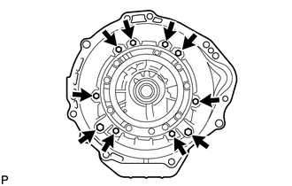
Remove the 10 bolts.
-
Remove the transmission housing.
-
-
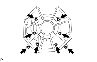
REMOVE REAR ADAPTOR TRANSFER
-
Remove the 8 bolts.
-
Remove the transmission case adapter.
Tech Tips
Use a brass bar and a hammer to remove the transmission case adapter.
-
-
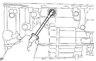
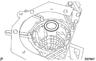
REMOVE TRANSMISSION CASE ADAPTER REAR OIL SEAL
-
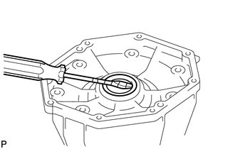
Using a screwdriver, pry out the oil seal.
Note
Be careful not to damage the transmission case.
Tech Tips
Wrap the tip of the screwdriver with tape.
-
-
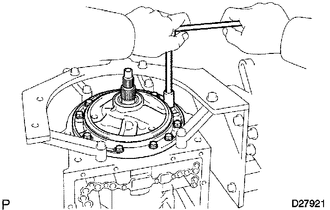
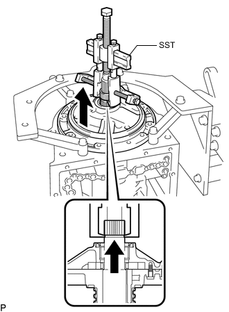
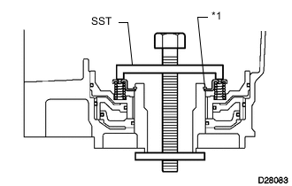
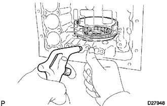
REMOVE TRANSFER CASE ADAPTER RADIAL BALL BEARING

-
Using a screwdriver, remove the snap ring.
-
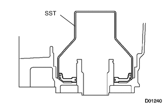
Using SST and a press, press out the bearing.
- SST
- 09950-60010 ( 09951-00650 )
- 09950-70010 ( 09951-07150 )
-
-
FIX AUTOMATIC TRANSMISSION CASE SUB-ASSEMBLY
-
Install the transmission case to an overhaul attachment.
-
-
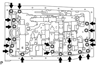
REMOVE AUTOMATIC TRANSMISSION OIL PAN SUB-ASSEMBLY
Note
Do not turn the transmission over as this will contaminate the valve body with foreign matter on the bottom of the pan.
-
Remove the drain plug and 20 bolts.
-
-
INSPECT AUTOMATIC TRANSMISSION OIL PAN SUB-ASSEMBLY
-
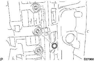
REMOVE VALVE BODY OIL STRAINER ASSEMBLY
-
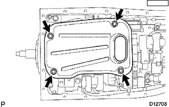
Turn over the transmission.
-
Remove the 4 bolts and oil strainer from the valve body.
-
Remove the O-ring from the oil strainer.
-
-
REMOVE TRANSMISSION WIRE
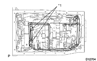
*1 Clamp
-
Remove the 2 bolts and 2 clamps, and disconnect the 2 ATF temperature sensors.
-
Disconnect the 7 connectors from the solenoid valves.
-
Remove the bolt from the case.
-
Pull the transmission wire out of the transmission case.
-
Remove the O-ring from the transmission wire.
-
-
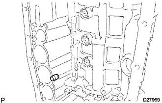
REMOVE TRANSMISSION VALVE BODY ASSEMBLY
-
Remove the bolt, detent spring cover and detent spring.
-
Remove the 19 bolts.
-
Remove the valve body.
-
-
REMOVE TRANSMISSION CASE GASKET
-
Remove the 3 gaskets.
-
-
REMOVE BRAKE DRUM GASKET
-
Remove the 3 gaskets.
-
-
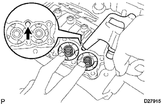
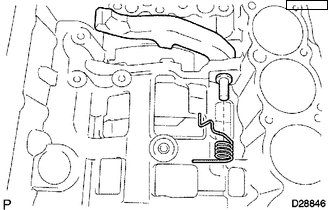
REMOVE CHECK BALL BODY
-
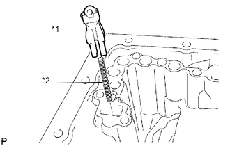
*1 Check Ball Body *2 Spring Remove the check ball body and spring.
-
-
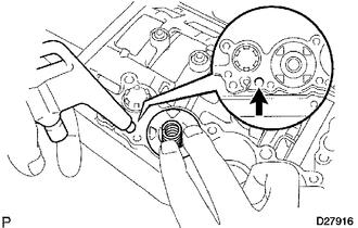
REMOVE C-2 ACCUMULATOR PISTON
-
Apply compressed air to the oil hole to remove the C-2 accumulator piston and spring.
-
Remove the 2 O-rings from the piston.
Note
Be careful as the C-3 and B-3 accumulator pistons may jump out.
-
-
REMOVE B-3 ACCUMULATOR PISTON
-
Apply compressed air to the oil hole to remove the B-3 accumulator piston and spring.
-
Remove the 2 O-rings from the piston.
Note
Be careful as the C-3 accumulator piston may jump out.
-
-
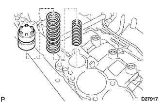
REMOVE C-3 ACCUMULATOR PISTON
-
Apply compressed air to the oil hole to remove the C-3 accumulator piston and 2 springs.
-
Remove the 2 O-rings from the piston.
-
-
REMOVE C-1 ACCUMULATOR VALVE
-
Remove the C-1 accumulator valve and 2 springs.
-
-
REMOVE PARKING LOCK PAWL BRACKET
-
Remove the 3 bolts and bracket.
-
-
REMOVE PARKING LOCK ROD SUB-ASSEMBLY
-
Disconnect the parking lock rod from the manual valve lever.
-
-
REMOVE PARKING LOCK PAWL SHAFT
-
Pull out the parking lock pawl shaft from the front side, and then remove the lock pawl and spring.
-
Remove the E-ring from the shaft.
-
-
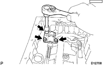
REMOVE MANUAL VALVE LEVER SUB-ASSEMBLY
-
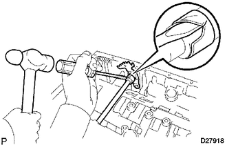
Using a hammer and screwdriver, cut off the spacer and remove it from the shaft.
-
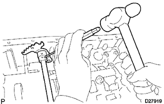
Using a pin punch and hammer, tap out the spring pin.
Tech Tips
Slowly drive out the spring pin so that it does not fall into the transmission case.
-
Pull the manual valve lever shaft out through the case, and remove the manual valve lever.
-
-
REMOVE MANUAL VALVE LEVER SHAFT OIL SEAL
-
Using a screwdriver, pry out the 2 oil seals.
Note
Be careful not to damage the transmission case.
Tech Tips
Wrap the tip of the screwdriver with tape.
-
-
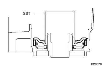
REMOVE OIL PUMP ASSEMBLY
-
Remove the 10 bolts.
-
Using SST, remove the oil pump.
- SST
- 09950-40011 ( 09951-04010, 09952-04010, 09953-04020, 09954-04010, 09955-04031, 09958-04011 )
-
Remove the 2 thrust bearing races from the front oil pump.
-
-
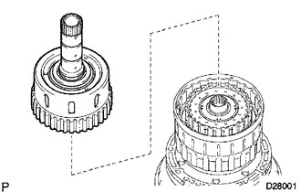
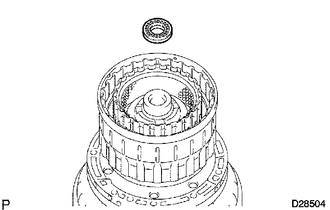
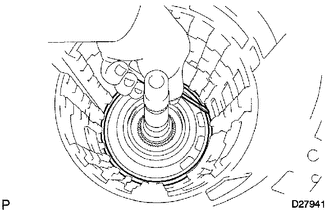
REMOVE CLUTCH DRUM AND INPUT SHAFT ASSEMBLY
-
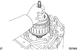
Remove the clutch drum and input shaft assembly from the transmission case.
-
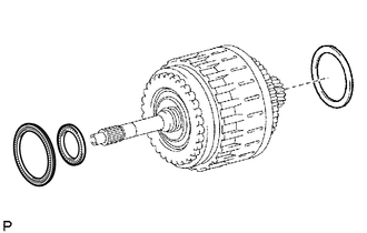
Remove the clutch drum thrust washer and 2 thrust needle roller bearings.
-
-
INSPECT NO. 2 1-WAY CLUTCH ASSEMBLY
-
REMOVE NO. 2 1-WAY CLUTCH ASSEMBLY
-
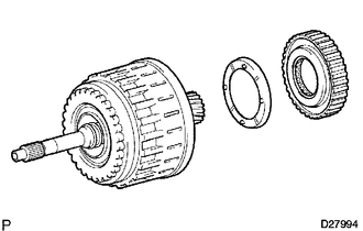
Remove the 1-way clutch and No. 2 clutch drum thrust washer from the clutch drum and input shaft assembly.
-
-
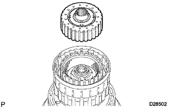
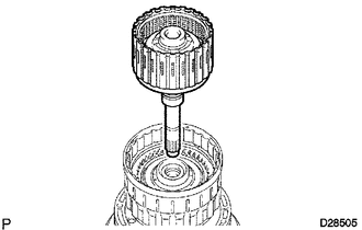
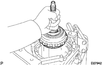
FIX CLUTCH DRUM AND INPUT SHAFT ASSEMBLY
-
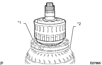
*1 Oil Pump *2 Torque Converter Clutch Place the oil pump onto the torque converter, and then place the clutch drum and input shaft assembly onto the oil pump.
-
-
REMOVE REVERSE CLUTCH HUB SUB-ASSEMBLY
-
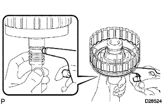
Using a screwdriver, remove the snap ring.
-
Remove the reverse clutch hub sub-assembly, reverse clutch reaction sleeve, clutch cushion, plate reverse clutch flange, 5 reverse clutch discs and 4 clutch plates from the clutch drum.
-
-
REMOVE REVERSE CLUTCH REACTION SLEEVE
-
Remove the reverse clutch reaction sleeve from the reverse clutch hub.
-
-
REMOVE REAR CLUTCH DISC
-
Remove the clutch cushion plate, reverse clutch flange, 5 discs and 4 plates from the reverse clutch hub.
-
-
INSPECT REAR CLUTCH DISC
-
INSPECT REVERSE CLUTCH HUB SUB-ASSEMBLY
-
REMOVE FORWARD CLUTCH HUB SUB-ASSEMBLY
-
Remove the forward clutch hub from the clutch drum.
-
Remove the 2 thrust needle roller bearings from the forward clutch hub.
-
-
INSPECT FORWARD CLUTCH HUB SUB-ASSEMBLY
-
REMOVE MULTIPLE DISC CLUTCH HUB
-
Remove the multiple disc clutch hub from the clutch drum.
-
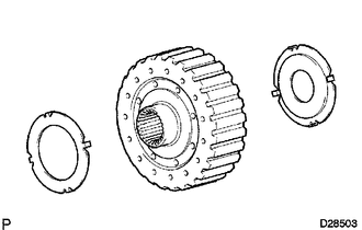
Remove the 2 thrust bearing races from the multiple disc clutch hub.
-
-
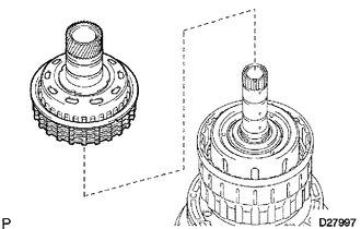
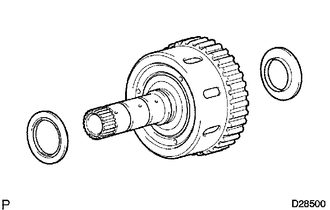
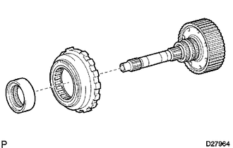
REMOVE INPUT SHAFT ASSEMBLY
-
Remove the thrust needle roller bearing from the clutch drum.
-
Remove the input shaft assembly from the clutch drum.
-
-
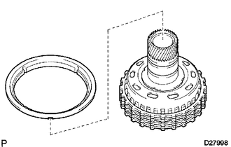
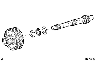
REMOVE INPUT SHAFT OIL SEAL RING
-
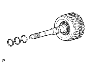
Remove the 3 oil seal rings from the input shaft.
-
-
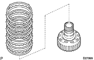
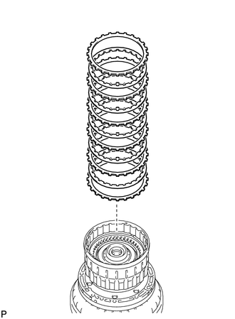
REMOVE FORWARD MULTIPLE DISC CLUTCH DISC
-
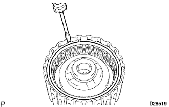
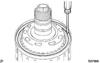
Using a screwdriver, remove the hole snap ring.
-
Remove the 2 flanges, 6 discs and 5 plates from the input shaft.
-
-
INSPECT FORWARD MULTIPLE DISC CLUTCH DISC
-
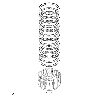
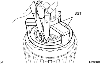
REMOVE NO. 1 CLUTCH BALANCER
-
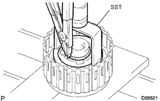
Place SST on the clutch balancer, and compress the return spring with a press.
- SST
- 09350-30020 ( 09350-07040, 09350-07070 )
-
Using a snap ring expander, remove the snap ring.
-
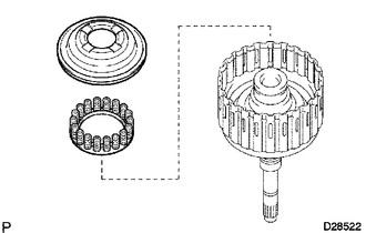
Remove the clutch balancer and forward clutch return spring from the input shaft assembly.
-
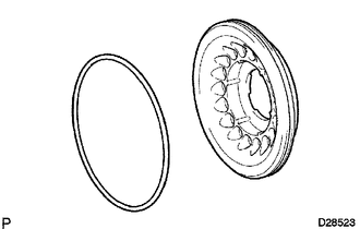
Remove the O-ring from the No. 1 clutch balancer.
-
-
INSPECT FORWARD CLUTCH RETURN SPRING SUB-ASSEMBLY
-
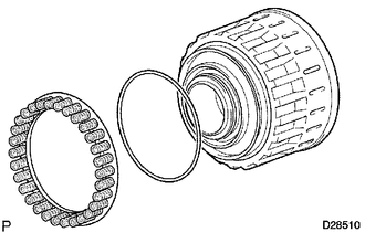
REMOVE FORWARD CLUTCH PISTON
-
Hold the input shaft by hand and apply compressed air (392 kPa (4.0 kgf/cm2, 57 psi)) to the input shaft to remove the forward clutch piston.
-
Remove the 2 O-rings from the forward clutch piston.
-
-
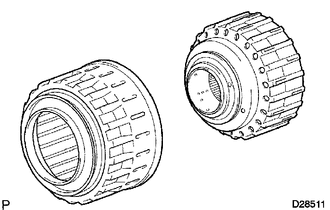
REMOVE REVERSE CLUTCH FLANGE
-
Remove the reverse clutch flange from the clutch drum.
-
-
REMOVE DIRECT CLUTCH DISC
-
Using a screwdriver, remove the 2 hole snap rings from the clutch drum.
-
Remove the reverse clutch flange, 5 discs and 5 plates from the clutch drum.
-
-
INSPECT DIRECT CLUTCH DISC
-
REMOVE NO. 3 CLUTCH BALANCER
-
Place SST on the clutch balancer, and compress the return spring with a press.
- SST
- 09387-00070
-
Using SST, remove the snap ring.
- SST
- 09350-30020 ( 09350-07070 )
-
-
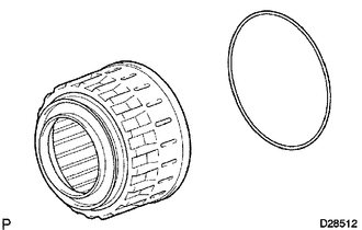
REMOVE REVERSE CLUTCH RETURN SPRING SUB-ASSEMBLY
-
Remove the reverse clutch return spring and O-ring from the reverse clutch piston.
-
-
INSPECT REVERSE CLUTCH RETURN SPRING SUB-ASSEMBLY
-
REMOVE REVERSE CLUTCH PISTON SUB-ASSEMBLY
-
Remove the reverse clutch piston sub-assembly from the clutch drum.
-
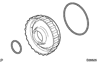
Remove the O-ring from the reverse clutch piston.
-
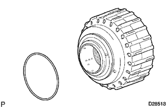
Remove the O-ring from the clutch drum.
-
-
REMOVE DIRECT CLUTCH PISTON SUB-ASSEMBLY
-
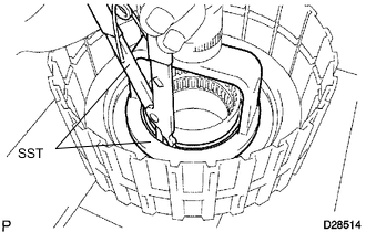
Place SST on the direct clutch piston, and compress the return spring with a press.
- SST
- 09320-89010
-
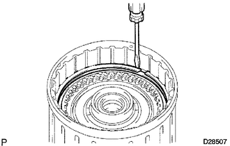
Using SST, remove the snap ring.
- SST
- 09350-30020 ( 09350-07070 )
-
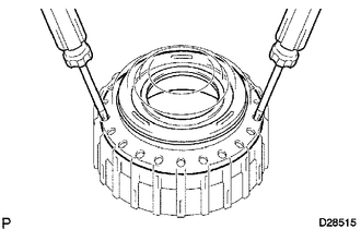
Using 2 screwdrivers, remove the direct clutch piston sub-assembly from the clutch drum.
-
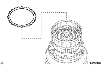
Remove the O-ring from the clutch drum.
-
Remove the No. 2 clutch balancer and direct clutch return spring from the direct clutch piston.
-
Remove the 2 O-rings from the direct clutch piston.
-
-
INSPECT DIRECT CLUTCH RETURN SPRING SUB-ASSEMBLY
-
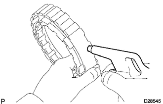
REMOVE NO. 3 BRAKE SNAP RING
-
Using a screwdriver, remove the No. 3 brake snap ring from the case.
-
-
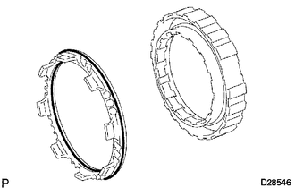
REMOVE NO. 3 BRAKE DISC
-
Remove the flange, 4 discs, 4 plates and cushion plate from the case.
-
-
INSPECT NO. 3 BRAKE DISC
-
REMOVE 2ND BRAKE PISTON HOLE SNAP RING
-
Using SST, remove the snap ring.
- SST
- 09350-30020 ( 09350-07060 )
-
-
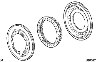
REMOVE 1-WAY CLUTCH ASSEMBLY
-
Remove the 1-way clutch assembly and No. 1 planetary carrier thrust washer from the case.
-
-
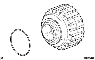
REMOVE 2ND BRAKE CYLINDER
-
Remove the 2nd brake cylinder from the case.
-
-
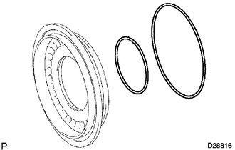
REMOVE 2ND BRAKE PISTON
-
Using SST and a press, compress the return spring and remove the snap ring.
- SST
- 09351-40010
-
Hold the 2nd brake cylinder and apply compressed air (392 kPa (4.0 kgf/cm2, 57 psi)) to the 2nd brake cylinder to remove the 2nd brake piston.
-
Remove the 2 O-rings from the 2nd brake piston.
-
-
INSPECT NO. 3 BRAKE PISTON RETURN SPRING SUB-ASSEMBLY
-
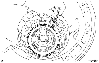
REMOVE FRONT PLANETARY GEAR ASSEMBLY
-
Remove the front planetary gear assembly and 1-way clutch inner race from the case.
-
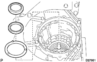
Remove the No. 5 thrust bearing race, thrust needle roller bearing and No. 2 planetary carrier thrust washer from the front planetary gear assembly.
-
-
INSPECT FRONT PLANETARY GEAR ASSEMBLY
-
INSPECT 1-WAY CLUTCH ASSEMBLY
-
REMOVE FRONT PLANETARY RING GEAR
-
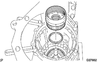
Remove the front planetary ring gear and thrust needle roller bearing from the transmission case.
-
-
REMOVE CENTER PLANETARY RING GEAR
-
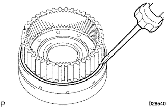
Using a screwdriver, remove the snap ring.
-
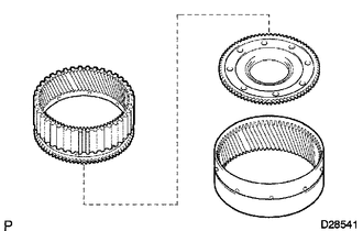
Remove the center planetary ring gear and front planetary ring gear flange from the front planetary ring gear.
-
-
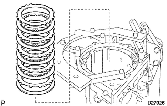
REMOVE NO. 1 BRAKE DISC
-
Remove the flange, 3 discs and 3 plates from the case.
-
-
INSPECT NO. 1 BRAKE DISC
-
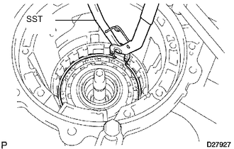
REMOVE BRAKE PISTON RETURN SPRING SNAP RING
-
Using a screwdriver, remove the brake piston return spring snap ring from the case.
-
-
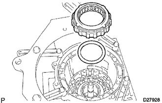
REMOVE BRAKE PISTON RETURN SPRING SUB-ASSEMBLY
-
Remove the brake piston return spring and No. 1 brake piston with No. 1 brake cylinder from the transmission case.
-
-
INSPECT BRAKE PISTON RETURN SPRING SUB-ASSEMBLY
-
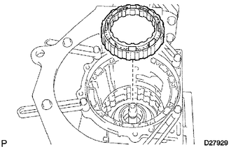
REMOVE NO. 1 BRAKE PISTON
-
Hold the No. 1 brake cylinder and apply compressed air (392 kPa (4.0 kgf/cm2, 57 psi)) to No. 1 brake cylinder to remove the No. 1 brake piston.
Tech Tips
If the piston does not pop out with compressed air, lift the piston out with needle-nose pliers.
-
Remove the 2 O-rings from the No. 1 brake piston.
-
-
REMOVE NO. 2 BRAKE DISC
-
Using a screwdriver, remove the snap ring from the case.
-
Remove the flange, 3 discs, 3 plates and brake piston return spring from the case.
-
-
INSPECT NO. 2 BRAKE DISC
-
INSPECT NO. 2 BRAKE PISTON RETURN SPRING SUB-ASSEMBLY
-
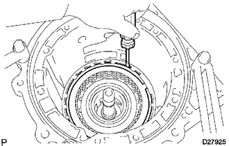
REMOVE NO. 2 BRAKE PISTON
-
Apply compressed air (392 kPa (4.0 kgf/cm2, 57 psi)) to the transmission case to remove the No. 2 brake piston.
Tech Tips
If the piston does not pop out with compressed air, lift the piston out with needle-nose pliers.
-
Remove the 2 O-rings from the No. 2 brake piston.
-
-
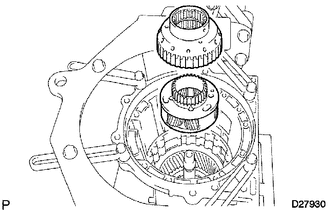
REMOVE CENTER PLANETARY GEAR ASSEMBLY
-
Remove the No. 6 thrust bearing race, center planetary gear and planetary sun gear from the case.
-
-
INSPECT CENTER PLANETARY GEAR ASSEMBLY
-
REMOVE INTERMEDIATE SHAFT
-
Using a screwdriver, remove the snap ring from the case.
-
Remove the intermediate shaft with No. 3 1-way clutch assembly from the case.
-
-
INSPECT NO. 3 1-WAY CLUTCH ASSEMBLY
-
REMOVE NO. 3 1-WAY CLUTCH ASSEMBLY
-
Remove the No. 3 1-way clutch assembly and 1-way clutch inner race from the intermediate shaft.
-
-
REMOVE REAR PLANETARY RING GEAR FLANGE SUB-ASSEMBLY
-
Remove the planetary ring gear flange, No. 7 thrust bearing race, thrust needle roller bearing and No. 8 thrust bearing race from the intermediate shaft.
-
-
INSPECT REAR PLANETARY RING GEAR FLANGE SUB-ASSEMBLY
-
INSPECT INTERMEDIATE SHAFT
-
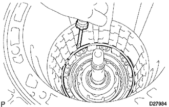
REMOVE BRAKE PLATE STOPPER SPRING
-
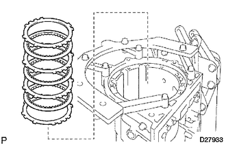
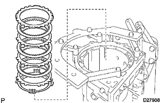
REMOVE NO. 4 BRAKE DISC
-
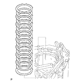
Remove the 7 plates, 8 discs and 2 flanges from the case.
-
-
INSPECT NO. 4 BRAKE DISC
-
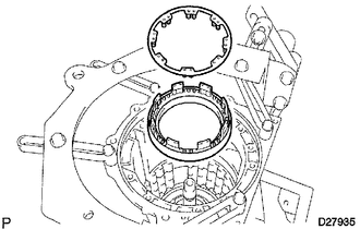
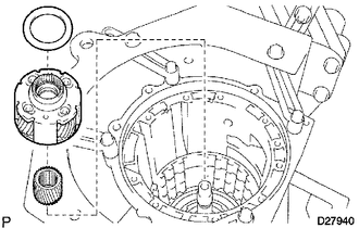
REMOVE REAR PLANETARY GEAR ASSEMBLY
-
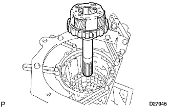
Remove the rear planetary gear assembly from the case.
-
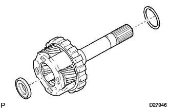
Remove the 2 thrust needle roller bearings from the rear planetary gear.
-
Remove the No. 9 thrust bearing from the case.
-
-
INSPECT REAR PLANETARY GEAR ASSEMBLY
-
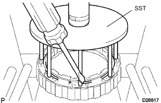
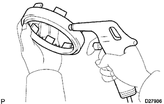
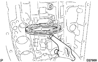
REMOVE 1ST AND REVERSE BRAKE RETURN SPRING SUB-ASSEMBLY
-
*1 Snap Ring Place SST on the spring retainer and compress the brake return spring.
- SST
- 09350-30020 ( 09350-07050 )
-
Using SST, remove the snap ring and brake return spring.
- SST
- 09350-30020 ( 09350-07070 )
-
-
INSPECT 1ST AND REVERSE BRAKE RETURN SPRING SUB-ASSEMBLY
-
REMOVE 1ST AND REVERSE BRAKE PISTON
-
Apply compressed air (392 kPa (4.0 kgf/cm2, 57 psi)) to the transmission case to remove the 1st and reverse brake piston.
Tech Tips
If the piston does not pop out with compressed air, lift the piston out with needle-nose pliers.
-
Remove the O-ring from the 1st and reverse brake piston.
-
-
REMOVE BRAKE REACTION SLEEVE
-
Using SST, remove the reaction sleeve.
- SST
- 09350-30020 ( 09350-07080 )
-
Remove the O-ring from the reaction sleeve.
-
-
REMOVE NO. 4 BRAKE PISTON
-
Using SST, remove the brake piston.
- SST
- 09350-30020 ( 09350-07090 )
-
Remove the 2 O-rings from the brake piston.
-