PROCEDURE
-
Table 1. *1 Lower Side *2 OutwardClick here
INSTALL OIL COOLER ASSEMBLY
-
Connect the oil cooler inlet hose and outlet hose.
-
Install the rear transmission oil cooler air duct with the 4 bolts, and then install the air cooled oil cooler tube to the transmission oil cooler air duct with the bolt.
4.9 N*m 50 kgf*cm 43 in.*lbf -
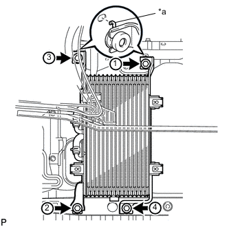
Table 2. *a Claw Temporarily put the oil cooler on the radiator support.
Note:Securely attach the 2 claws of the oil cooler into the holes of the radiator support.
-
Install the 4 bolts in the sequence shown in the illustration.
12 N*m 122 kgf*cm 9 ft.*lbf
-
- Click here
INSTALL TRANSMISSION OIL COOLER AIR DUCT
-
Install the oil cooler air duct with the 4 bolts.
4.9 N*m 50 kgf*cm 43 in.*lbf
-
-
Click here
INSTALL OIL COOLER TUBE SUB-ASSEMBLY
-
Temporarily install the oil cooler tube to the fan shroud with bolt A. Install bolt B and tighten it to the specified torque. Then tighten bolt A to the specified torque.
5.0 N*m 51 kgf*cm 44 in.*lbf
-
-
Table 3. *1 Paint MarkClick here
CONNECT INLET NO. 4 OIL COOLER HOSE
-
Connect the inlet oil cooler hose as shown in the illustration.
Note:Make sure the pinching portion of each clip is facing the direction shown in the illustration and the paint marks are aligned as shown in the illustration.
-
-
Click here
CONNECT INLET NO. 2 OIL COOLER HOSE AND INLET NO. 3 OIL COOLER HOSE
-
Connect the 2 transmission oil cooler hoses as shown in the illustration.
Note:Make sure the pinching portion of each clip is facing the direction shown in the illustration.
-
-
Table 4. *1 Paint MarkClick here
CONNECT INLET NO. 1 OIL COOLER HOSE AND OUTLET NO. 1 OIL COOLER HOSE
-
Connect the 2 oil cooler hoses as shown in the illustration.
Note:Make sure the pinching portion of each clip is facing the direction shown in the illustration and the paint marks are aligned as shown in the illustration.
-
Pass the hose through the flexible hose clamp and close the clamp shown in the illustration.
-
-
Table 5. *1 RH Side *2 Paint MarkClick here
CONNECT TRANSMISSION OIL COOLER HOSE
-
Connect the 2 transmission oil cooler hoses as shown in the illustration.
Note:Make sure the pinching portion of each clip is facing the direction shown in the illustration.
-
- Click here
ADD AUTOMATIC TRANSMISSION FLUID
-
Add automatic transmission fluid (Click here).
-
- Click here
INSTALL HEADLIGHT ASSEMBLY RH
for Standard: (Click here)
for HID Headlight: (Click here)
- Click here
INSTALL FRONT FENDER APRON TRIM PACKING C
- Click here
INSTALL FRONT FENDER APRON TRIM PACKING A
- Click here
INSTALL NO. 2 ENGINE UNDER COVER
- Click here
INSTALL NO. 1 ENGINE UNDER COVER
- Click here
INSTALL FRONT FENDER SPLASH SHIELD SUB-ASSEMBLY LH
- Click here
INSTALL FRONT FENDER SPLASH SHIELD SUB-ASSEMBLY RH