FORWARD RECOGNITION CAMERA SYSTEM, Diagnostic DTC:C1AAE
| DTC Code | DTC Name |
|---|---|
| C1AAE | Heater Circuit |
DESCRIPTION
The forward recognition camera turns the forward recognition with heater hood sub-assembly on or off.
C1AAE is stored when the forward recognition camera detects a malfunction in the forward recognition with heater hood sub-assembly circuit.
| DTC No. | DTC Detection Condition | Trouble Area |
|---|---|---|
| C1AAE |
Either of the following conditions is met after 2 seconds have elapsed since the engine switch was turned on (IG): |
|
WIRING DIAGRAM
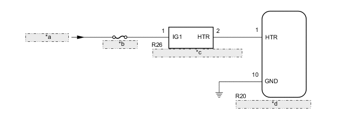
| *a | from IG Circuit |
| *b | ECU-IG NO. 3 |
| *c | Forward Recognition with Heater Hood Sub-assembly |
| *d | Forward Recognition Camera |
CAUTION / NOTICE / HINT
Note
-
Inspect the fuses for circuits related to this system before performing the following procedure.
-
When replacing the forward recognition camera, always replace it with a new one. If a forward recognition camera which was installed to another vehicle is used, the information stored in the forward recognition camera will not match the information from the vehicle. As a result, a DTC may be stored.
-
If the forward recognition camera has been replaced with a new one, be sure to perform forward recognition camera learning.
PROCEDURE
-
CHECK DTC OUTPUT (FORWARD RECOGNITION CAMERA SYSTEM)
-
Connect the GTS to the DLC3.
-
Turn the engine switch on (IG).
-
Turn the GTS on.
-
Enter the following menus: Chassis / Front Recognition Camera / Trouble Codes.
-
Clear the DTCs.
-
Make sure that the DTC detection conditions are met.
Tech Tips
If the conditions are not met, the system cannot detect the malfunction.
-
Turn the engine switch on (IG) and wait 7 seconds or more.
-
-
Check for DTCs.
Result Result Proceed to DTC C1AAE is not output A DTC C1AAE is output B
A 
USE SIMULATION METHOD TO CHECK Click here
B 
-
-
INSPECT FORWARD RECOGNITION WITH HEATER HOOD SUB-ASSEMBLY
-
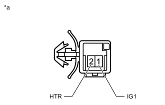
*a Component without harness connected
(Forward Recognition with Heater Hood Sub-assembly)
Disconnect the R26 forward recognition with heater hood sub-assembly connector.
-
Measure the resistance according to the value(s) in the table below.
Standard Resistance Tester Connection Condition Specified Condition 1 (IG1) - 2 (HTR) Always 38 to 42 Ω Result Proceed to OK NG
NG
REPLACE FORWARD RECOGNITION WITH HEATER HOOD SUB-ASSEMBLY Click here
OK
-
-
CHECK TERMINAL VOLTAGE (FORWARD RECOGNITION WITH HEATER HOOD SUB-ASSEMBLY POWER SOURCE VOLTAGE)
-
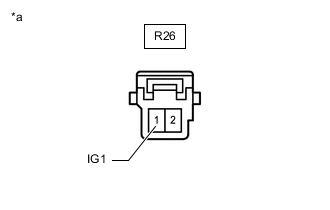
*a Front view of wire harness connector
(to Forward Recognition with Heater Hood Sub-assembly)
Disconnect the R26 forward recognition with heater hood sub-assembly connector.
-
Measure the voltage according to the value(s) in the table below.
Standard Voltage Tester Connection Condition Specified Condition R26-1(IG1) - Body ground Engine switch on (IG) 11 to 14 V Engine switch off Below 1 V Result Proceed to OK NG
NG
REPAIR OR REPLACE HARNESS OR CONNECTOR
OK
-
-
CHECK HARNESS AND CONNECTOR (FORWARD RECOGNITION WITH HEATER HOOD SUB-ASSEMBLY - FORWARD RECOGNITION CAMERA)
-
Disconnect the R20 forward recognition camera connector.
-
Disconnect the R26 forward recognition with heater hood sub-assembly connector.
-
Measure the resistance according to the value(s) in the table below.
Standard Resistance Tester Connection Condition Specified Condition R20-1 (HTR) - R26-2 (HTR) Always Below 1 Ω R20-1 (HTR) or R26-2 (HTR) - Body ground Always 10 kΩ or higher Result Proceed to OK NG
NG
REPAIR OR REPLACE HARNESS OR CONNECTOR
OK
-
-
CHECK HARNESS AND CONNECTOR (FORWARD RECOGNITION CAMERA - BODY GROUND)
-
Disconnect the R20 forward recognition camera connector.
-
Measure the resistance according to the value(s) in the table below.
Standard Resistance Tester Connection Condition Specified Condition R20-10 (GND) - Body ground Always Below 1 Ω Result Proceed to OK NG
OK
REPLACE FORWARD RECOGNITION CAMERA Click here
NG
REPAIR OR REPLACE HARNESS OR CONNECTOR
-