CRUISE CONTROL SYSTEM Cruise Main Indicator Light Circuit
DESCRIPTION
-
The ECM detects a cruise control switch signal and sends it to the combination meter via the CAN communication line. Then the cruise control indicator light comes on.
-
The cruise control indicator light circuit uses the CAN for communication. If there is a malfunction in this circuit, check for DTCs in the CAN communication system before troubleshooting this circuit.
WIRING DIAGRAM
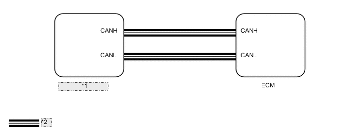
| *1 | Combination Meter |
| *2 | CAN Communication Line |
PROCEDURE
-
PERFORM ACTIVE TEST USING INTELLIGENT TESTER (CRUISE CONTROL INDICATOR LIGHT)
-
Using the intelligent tester, perform the Active Test Click here.
Combination Meter Tester Display Test Part Control Range Diagnostic Note Indicat. Lamp Cruise Cruise control indicator light operation OFF / ON - OK Indicator light comes on/goes off. Result Result Proceed to OK A NG
(w/ Multi-information Display)
B NG
(w/o Multi-information Display)
C
B 
REPLACE COMBINATION METER ASSEMBLY Click here
C
REPLACE COMBINATION METER ASSEMBLY Click here
A 
-
-
READ VALUE USING INTELLIGENT TESTER (CRUISE CONTROL INDICATOR LIGHT)
-
Using the intelligent tester, read the Data List Click here.
Cruise Control Tester Display Measurement Item/Range Normal Condition Diagnostic Note CCS Indicator M-CPU Cruise control indicator light (Main CPU) / ON or OFF ON: Cruise control indicator light is on
OFF: Cruise control indicator light is off
- OK The intelligent tester display changes according to condition of cruise control indicator light. Result Result Proceed to OK A NG
(for 1GR-FE)
B NG
(for 1UR-FE)
C NG
(for 3UR-FE)
D NG
(for 1VD-FTV)
E
A
PROCEED TO NEXT CIRCUIT INSPECTION SHOWN IN PROBLEM SYMPTOMS TABLE Click here
B
REPLACE ECM Click here
C
REPLACE ECM Click here
D
REPLACE ECM Click here
E
REPLACE ECM Click here
-