CRUISE CONTROL SYSTEM Cruise Control Switch Circuit
DESCRIPTION
The cruise control main switch is used to turn the cruise control system on and off, as well as operate 7 functions: SET, - (COAST), TAP-DOWN, RES (RESUME), + (ACCEL), TAP-UP and CANCEL. The SET, TAP-DOWN and - (COAST) functions, and the RES (RESUME), TAP-UP and + (ACCEL) functions are operated with the same switch. The cruise control main switch is an automatic return type switch which turns on only while operating it in the direction of each arrow and turns off after releasing it. The internal contact points of the cruise control main switch turn on with switch operation. Then the ECM reads the voltage value that has been changed by the switch operation to control the SET, - (COAST), RES (RESUME), + (ACCEL), and CANCEL functions.
WIRING DIAGRAM
PROCEDURE
-
READ VALUE USING GTS (CRUISE CONTROL MAIN SWITCH)
-
Use the Data List to check if the cruise control main switch is functioning properly Click here.
Cruise Control Tester Display Measurement Item/Range Normal Condition Diagnostic Note Cancel Switch CANCEL switch status / ON or OFF ON: CANCEL switch on
OFF: CANCEL switch off
- -SET Switch -/SET switch status / ON or OFF ON: -/SET switch on
OFF: -/SET switch off
- +RES Switch +/RES switch status / ON or OFF ON: +/RES switch on
OFF: +/RES switch off
- Cruise Ready Main-CPU Cruise control system standby condition / ON or OFF Each time cruise control main switch (ON/OFF) is pushed, ON or OFF changes - Cruise Ready Sub-CPU Cruise control system standby condition / ON or OFF Each time cruise control main switch (ON/OFF) is pushed, ON or OFF changes - OK The Data List items shown in the table change according to the operation of the cruise control main switch.
OK 
PROCEED TO NEXT SUSPECTED AREA SHOWN IN PROBLEM SYMPTOMS TABLE Click here
NG 
-
-
INSPECT CRUISE CONTROL MAIN SWITCH
-
Remove the cruise control main switch Click here.
-
Inspect the cruise control main switch Click here.
NG
REPLACE CRUISE CONTROL MAIN SWITCH Click here
OK
-
-
INSPECT CRUISE CONTROL SWITCH WIRE
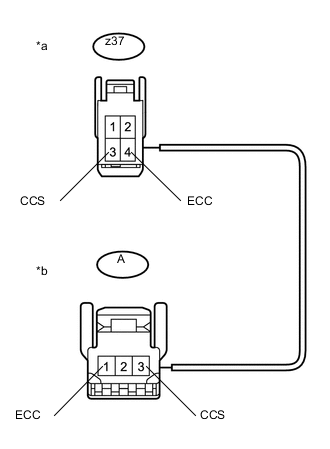
Text in Illustration *a Front view of wire harness connector
(to Spiral Cable Sub-assembly)
*b Front view of wire harness connector
(to Cruise Control Main Switch)
-
Disconnect the z37 spiral cable sub-assembly connector.
-
Disconnect the A cruise control main switch connector.
-
Measure the resistance according to the value(s) in the table below.
Standard Resistance Tester Connection Condition Specified Condition z37-3 (CCS) - A-3 (CCS) Always Below 1 Ω z37-4 (ECC) - A-1 (ECC) z37-3 (CCS) - Body ground Always 10 kΩ or higher z37-4 (ECC) - Body ground
NG
REPLACE CRUISE CONTROL SWITCH WIRE Click here
OK
-
-
INSPECT SPIRAL CABLE SUB-ASSEMBLY
-
Remove the spiral cable sub-assembly Click here.
-
Inspect the spiral cable sub-assembly Click here.
NG
REPLACE SPIRAL CABLE SUB-ASSEMBLY Click here
OK
-
-
CHECK HARNESS AND CONNECTOR (SPIRAL CABLE SUB-ASSEMBLY - ECM AND BODY GROUND)
-
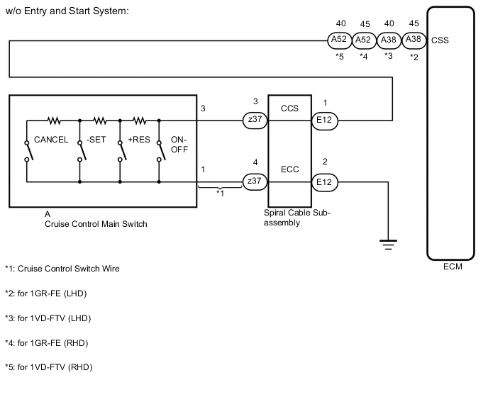
w/o Entry and Start System:
-
Disconnect the E12 spiral cable sub-assembly connector.
-
Disconnect the A38*1 or A52*2 ECM connector.
-
*1: for 1GR-FE (LHD) and 1VD-FTV (LHD)
-
*2: for 1GR-FE (RHD) and 1VD-FTV (RHD)
-
-
Measure the resistance according to the value(s) in the table below.
Standard Resistance Tester Connection Condition Specified Condition E12-1 (CCS) - A38-45 (CCS)*1 Always Below 1 Ω E12-1 (CCS) - A38-40 (CCS)*2 E12-1 (CCS) - A52-45 (CCS)*3 E12-1 (CCS) - A52-40 (CCS)*4 E12-2 (ECC) - Body ground E12-1 (CCS) or A38-45 (CCS)*1 - Body ground Always 10 kΩ or higher E12-1 (CCS) or A38-40 (CCS)*2 - Body ground E12-1 (CCS) or A52-45 (CCS)*3 - Body ground E12-1 (CCS) or A52-40 (CCS)*4 - Body ground
-
*1: for 1GR-FE (LHD)
-
*2: for 1VD-FTV (LHD)
-
*3: for 1GR-FE (RHD)
-
*4: for 1VD-FTV (RHD)
-
-
-
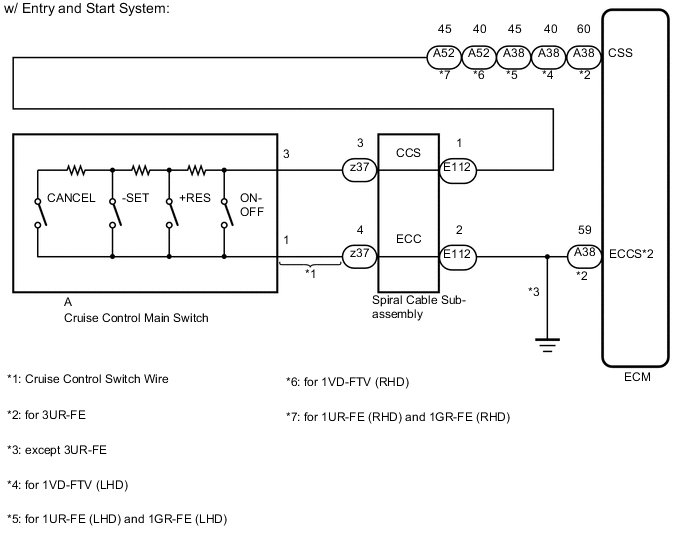
w/ Entry and Start System:
-
Disconnect the E112 spiral cable sub-assembly connector.
-
Disconnect the A38*1 or A52*2 ECM connector.
-
*1: for 3UR-FE, 1UR-FE (LHD), 1VD-FTV (LHD) and 1GR-FE (LHD)
-
*2: for 1UR-FE (RHD), 1GR-FE (RHD) and 1VD-FTV (RHD)
-
-
Measure the resistance according to the value(s) in the table below.
Standard Resistance Tester Connection Condition Specified Condition E112-1 (CCS) - A38-60 (CCS)*1 Always Below 1 Ω E112-1 (CCS) - A38-40 (CCS)*2 E112-1 (CCS) - A38-45 (CCS)*3 E112-1 (CCS) - A52-40 (CCS)*4 E112-1 (CCS) - A52-45 (CCS)*5 E112-2 (ECC) - Body ground E112-1 (CCS) or A38-60 (CCS)*1 - Body ground Always 10 kΩ or higher E112-1 (CCS) or A38-40 (CCS)*2 - Body ground E112-1 (CCS) or A38-45 (CCS)*3 - Body ground E112-1 (CCS) or A52-40 (CCS)*4 - Body ground E112-1 (CCS) or A52-45 (CCS)*5 - Body ground
-
*1: for 3UR-FE
-
*2: for 1VD-FTV (LHD)
-
*3: for 1UR-FE (LHD) and 1GR-FE (LHD)
-
*4: for 1VD-FTV (RHD)
-
*5: for 1UR-FE (RHD) and 1GR-FE (RHD)
-
Result Result Proceed to OK (for 1GR-FE) A OK (for 1VD-FTV) B OK (for 1UR-FE) C OK (for 3UR-FE) D NG E -
A
REPLACE ECM Click here
B
REPLACE ECM Click here
C
REPLACE ECM Click here
D
REPLACE ECM Click here
E
REPAIR OR REPLACE HARNESS OR CONNECTOR
-