CRUISE CONTROL SYSTEM, Diagnostic DTC:P0571
| DTC Code | DTC Name |
|---|---|
| P0571 | Brake Switch "A" Circuit |
DESCRIPTION
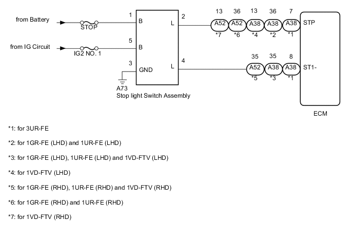
When the brake pedal is depressed, the stop light switch assembly sends a signal to the ECM. When the ECM receives this signal, it cancels control of vehicle speed by the cruise control system. The fail-safe function operates to enable normal driving even if there is a malfunction in the stop light switch assembly signal circuit. The cancellation condition occurs when voltage is applied to terminal STP. When the brake pedal is depressed, voltage is applied to terminal STP of the ECM through the STOP fuse and the stop light switch assembly, and the ECM cancels control of vehicle speed by the cruise control system.
| DTC Code | DTC Detection Condition | Trouble Area |
|---|---|---|
| P0571 | When voltage of STP terminal and that of ST1- terminal of ECM are less than 1 V for 0.5 seconds or more. |
|
WIRING DIAGRAM
CAUTION / NOTICE / HINT
Note
Inspect the fuses for circuits related to this system before performing the following inspection procedure.
PROCEDURE
-
CHECK HARNESS AND CONNECTOR (STOP LIGHT SWITCH ASSEMBLY - BATTERY AND BODY GROUND)
-
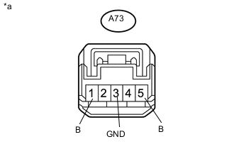
Text in Illustration *a Front view of wire harness connector
(to Stop Light Switch Assembly)
Disconnect the stop light switch assembly connector.
-
Measure the resistance according to the value(s) in the table below.
Standard Resistance Tester Connection Condition Specified Condition A73-3 (GND) - Body ground Always Below 1 Ω -
Measure the voltage according to the value(s) in the table below.
Standard Voltage Tester Connection Condition Specified Condition A73-5 (B) - Body ground Ignition switch ON 11 to 14 V Ignition switch off Below 1 V A73-1 (B) - Body ground Always 11 to 14 V
NG 
REPAIR OR REPLACE HARNESS OR CONNECTOR
OK 
-
-
CHECK HARNESS AND CONNECTOR (STOP LIGHT SWITCH ASSEMBLY INPUT CIRCUIT)
-
for 3UR-FE:
-
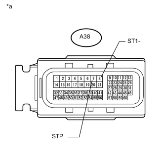
Text in Illustration *a Front view of wire harness connector
(to ECM)
Disconnect the ECM connector.
-
Measure the voltage according to the value(s) in the table below.
Standard Voltage Tester Connection Condition Specified Condition A38-8 (ST1-) - Body ground Ignition switch ON, brake pedal released 7.5 to 14 V Ignition switch ON, brake pedal depressed 0 to 1.5 V A38-7 (STP) - Body ground Brake pedal released 0 to 1.5 V Brake pedal depressed 7.5 to 14 V
-
-
for 1UR-FE (LHD) and 1GR-FE (LHD):
-
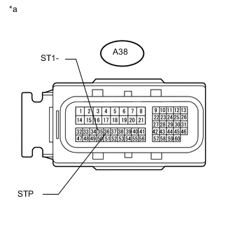
Text in Illustration *a Front view of wire harness connector
(to ECM)
Disconnect the ECM connector.
-
Measure the voltage according to the value(s) in the table below.
Standard Voltage Tester Connection Condition Specified Condition A38-35 (ST1-) - Body ground Ignition switch ON, brake pedal released 7.5 to 14 V Ignition switch ON, brake pedal depressed 0 to 1.5 V A38-36 (STP) - Body ground Brake pedal released 0 to 1.5 V Brake pedal depressed 7.5 to 14 V
-
-
for 1UR-FE (RHD) and 1GR-FE (RHD):
-
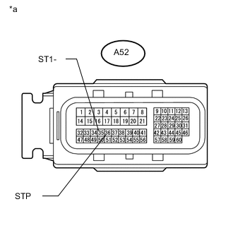
Text in Illustration *a Front view of wire harness connector
(to ECM)
Disconnect the ECM connector.
-
Measure the voltage according to the value(s) in the table below.
Standard Voltage Tester Connection Condition Specified Condition A52-35 (ST1-) - Body ground Ignition switch ON, brake pedal released 7.5 to 14 V Ignition switch ON, brake pedal depressed 0 to 1.5 V A52-36 (STP) - Body ground Brake pedal released 0 to 1.5 V Brake pedal depressed 7.5 to 14 V
-
-
for 1VD-FTV (LHD):
-
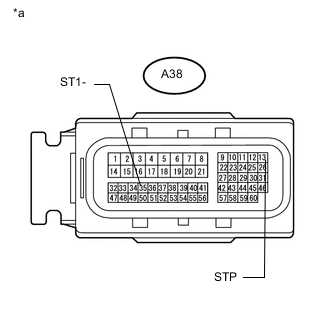
Text in Illustration *a Front view of wire harness connector
(to ECM)
Disconnect the ECM connector.
-
Measure the voltage according to the value(s) in the table below.
Standard Voltage Tester Connection Condition Specified Condition A38-35 (ST1-) - Body ground Ignition switch ON, brake pedal released 7.5 to 14 V Ignition switch ON, brake pedal depressed 0 to 1.5 V A38-13 (STP) - Body ground Brake pedal released 0 to 1.5 V Brake pedal depressed 7.5 to 14 V
-
-
for 1VD-FTV (RHD):
-

Text in Illustration *a Front view of wire harness connector
(to ECM)
Disconnect the ECM connector.
-
Measure the voltage according to the value(s) in the table below.
Standard Voltage Tester Connection Condition Specified Condition A52-35 (ST1-) - Body ground Ignition switch ON, brake pedal released 7.5 to 14 V Ignition switch ON, brake pedal depressed 0 to 1.5 V A52-13 (STP) - Body ground Brake pedal released 0 to 1.5 V Brake pedal depressed 7.5 to 14 V
-
NG
REPAIR OR REPLACE HARNESS OR CONNECTOR
OK
-
-
CHECK STOP LIGHT SWITCH ASSEMBLY
-
Temporarily replace the stop light switch assembly with a new or normally functioning one Click here.
-
Connect the GTS to the DLC3.
-
Turn the ignition switch to ON.
-
Turn the GTS on.
-
Enter the following menus: Powertrain / Cruise Control / Trouble Codes.
-
Clear the DTCs Click here.
-
Make sure that the DTC detection conditions are met.
Tech Tips
If the following procedure is not performed, the previously output DTC cannot be detected.
-
Drive the vehicle at a speed for which cruise control operation is possible.
-
Turn the cruise control system on using the cruise control main switch (ON/OFF).
-
Push the cruise control main switch to -/SET to begin control of vehicle speed using the cruise control system.
-
-
Check for DTCs Click here.
Result Result Proceed to DTC P0571 is not output A DTC P0571 is output (for 1GR-FE) B DTC P0571 is output (for 1VD-FTV) C DTC P0571 is output (for 1UR-FE) D DTC P0571 is output (for 3UR-FE) E
A
END (STOP LIGHT SWITCH ASSEMBLY WAS DEFECTIVE)
B
REPLACE ECM Click here
C
REPLACE ECM Click here
D
REPLACE ECM Click here
E
REPLACE ECM Click here
-