CAN COMMUNICATION SYSTEM(for LHD with Central Gateway ECU) SYSTEM DIAGRAM
-
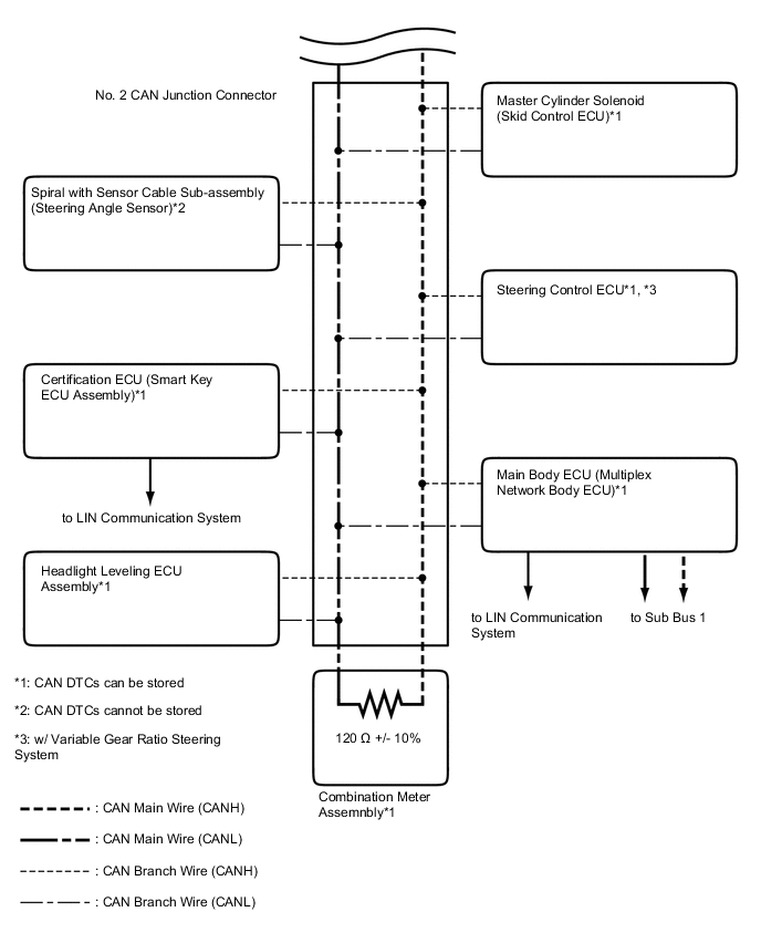
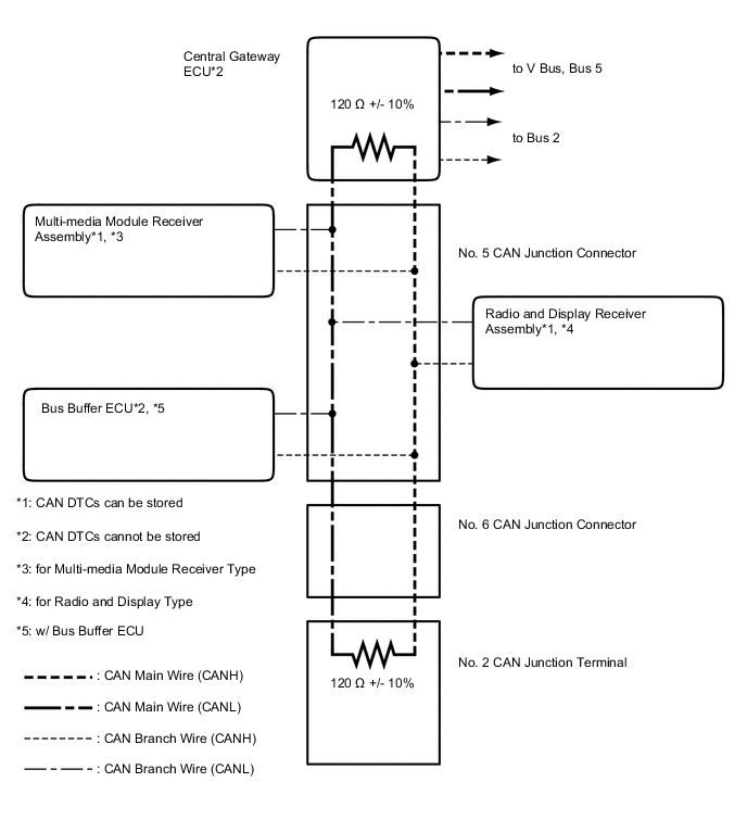
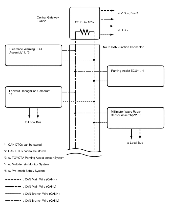
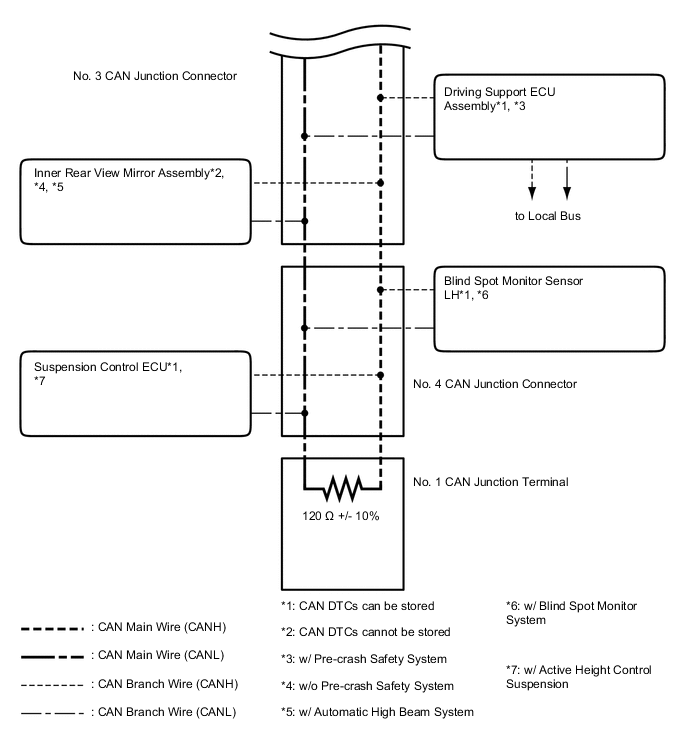
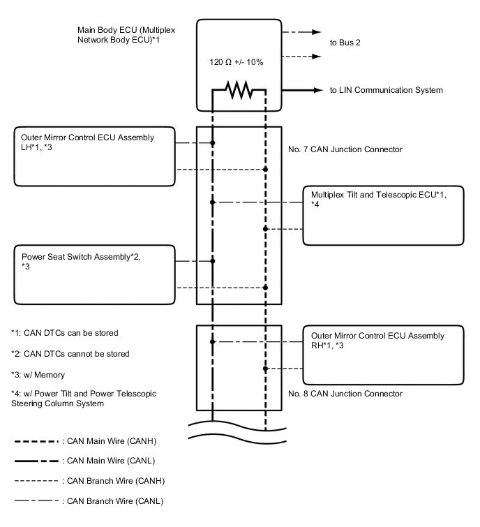
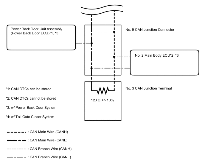
SYSTEM DIAGRAM
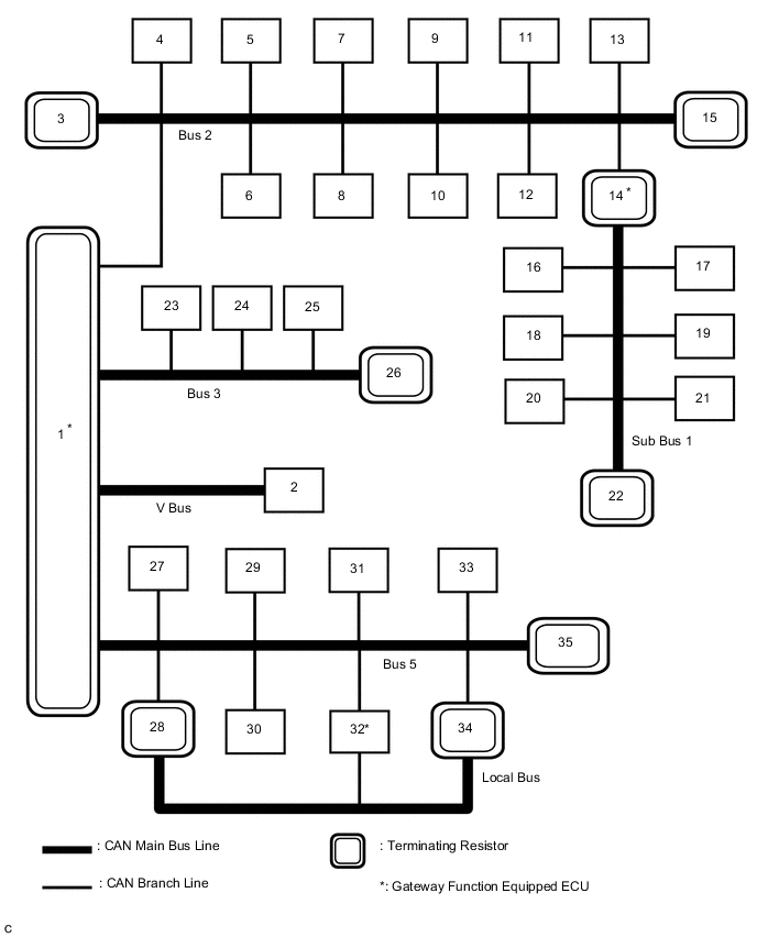
No. ECU/Sensor name 1 Central Gateway ECU 2 DLC3 3 ECM 4 4WD Control ECU 5 Tire Pressure Warning ECU*1 6 Airbag Sensor Assembly 7 Air Conditioning Amplifier Assembly 8 Headlight Leveling ECU Assembly 9 Master Cylinder Solenoid (Skid Control ECU) 10 Steering Control ECU*2 11 Certification ECU (Smart Key ECU Assembly)*3 12 Power Steering ECU Assembly*4 13 Spiral with Sensor Cable Sub-assembly (Steering Angle Sensor) 14 Main Body ECU (Multiplex Network Body ECU) 15 Combination Meter Assembly 16 Outer Mirror Control ECU Assembly RH*5 17 Outer Mirror Control ECU Assembly LH*5 18 Power Seat Switch Assembly*5 19 Multiplex Tilt and Telescopic ECU*6 20 Power Back Door Unit Assembly (Power Back Door ECU)*7 21 No. 2 Main Body ECU*8 22 No. 3 CAN Junction Terminal 23 Multi-media Module Receiver Assembly*9 24 Radio and Display Receiver Assembly*10 25 Bus Buffer ECU*11 26 No. 2 CAN Junction Terminal 27 Clearance Warning ECU Assembly*12 28 Forward Recognition Camera*14 29 Parking Assist ECU*13 30 Inner Rear View Mirror Assembly*15, *16 31 Suspension Control ECU*17 32 Driving Support ECU Assembly*14 33 Blind Spot Monitor Sensor LH*18 34 Millimeter Wave Radar Sensor Assembly*14 35 No. 1 CAN Junction Terminal
-
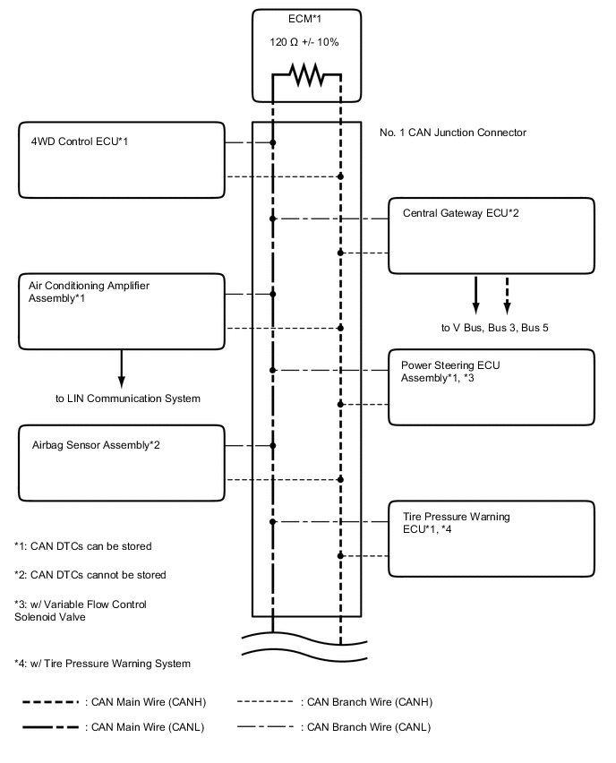
*1: w/ Tire Pressure Warning System
-
*2: w/ Variable Gear Ratio Steering System
-
*3: w/ Entry and Start System
-
*4: w/ Variable Flow Control Solenoid Valve
-
*5: w/ Memory
-
*6: w/ Power Tilt and Power Telescopic Steering Column System
-
*7: w/ Power Back Door System
-
*8: w/ Tail Gate Closer System
-
*9: for Multi-media Module Receiver Type
-
*10: for Radio and Display Type
-
*11: w/ Bus Buffer ECU
-
*12: w/ TOYOTA Parking Assist-sensor System
-
*13: w/ Multi-terrain Monitor System
-
*14: w/ Pre-crash Safety System
-
*15: w/o Pre-crash Safety System
-
*16: w/ Automatic High Beam System
-
*17: w/ Active Height Control Suspension
-
*18: w/ Blind Spot Monitor System
Tech Tips
-
The main body ECU (multiplex network body ECU) functions as a gateway between the bus 2 and sub bus 1.
-
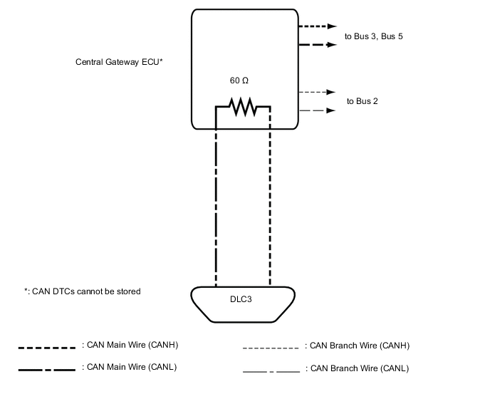
The central gateway ECU functions as a gateway between the V bus, bus 2, bus 3 and bus 5.
-
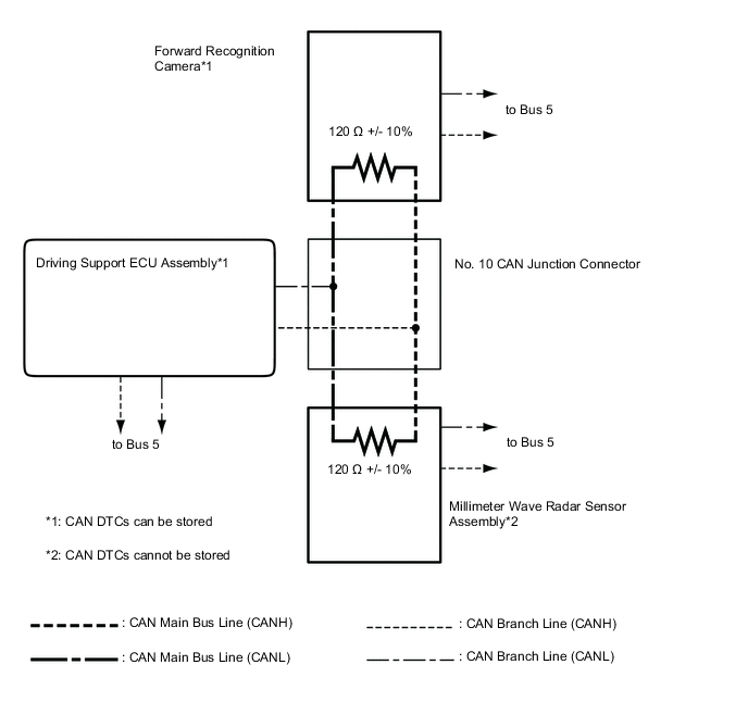
The driving support ECU assembly functions as a gateway between the bus 5 and local bus.
-
Refer to the following bus wiring diagrams for details.
-
-
V BUS
-
BUS 2
-
BUS 3
-
BUS 5
-
SUB BUS 1
-
LOCAL BUS (w/ Pre-crash Safety System)