CAN COMMUNICATION SYSTEM(for RHD), Diagnostic DTC:U1002 (CAN No. 2 BUS)
| DTC Code | DTC Name |
|---|---|
| U1002 (CAN No. 2 BUS) | Lost Communication with Gateway Module (Network Gateway ECU) |
DESCRIPTION
-
The network gateway ECU stores this DTC when no signals can be received from the ECUs that have been memorized as those connected to the CAN movement control bus.
-
When the network gateway ECU receives a response signal from the ECUs connected to the CAN movement control bus, the network gateway ECU recognizes and memorizes that the ECU is connected to the CAN movement control bus. Based on this memorized data, the network gateway ECU monitors for malfunctions in the ECUs connected to the CAN movement control bus when communicating with those ECUs. If the network gateway ECU cannot receive response signals from the ECUs that have been memorized as those connected to the CAN movement control bus, the network gateway ECU determines that a malfunction exists.
-
If 2 or more DTCs are output during the DTC check, one side of the CAN branch wire may be open (one side of the CANH [CAN branch wire]/CANL [CAN branch wire] of the ECU and/or sensor is open).
| DTC Code | DTC Detection Condition | Trouble Area |
|---|---|---|
| U1002 (CAN No. 2 BUS) | Lost communication with the gateway module (network gateway ECU). |
|
-
*1: for 1VD-FTV with DPF
-
*2: w/ Vehicle Stability Control System
-
*3: w/ Dynamic Radar Cruise Control System
-
*4: w/ Pre-crash Safety System
-
*5: w/ Side Monitor System
-
*6: w/ TOYOTA Parking Assist-sensor System and w/o Side Monitor System
-
*7: w/ Variable Gear Ratio Steering System
-
*8: w/ Active Height Control Suspension System
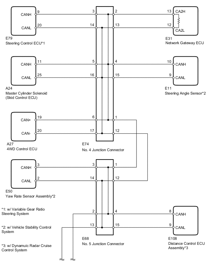
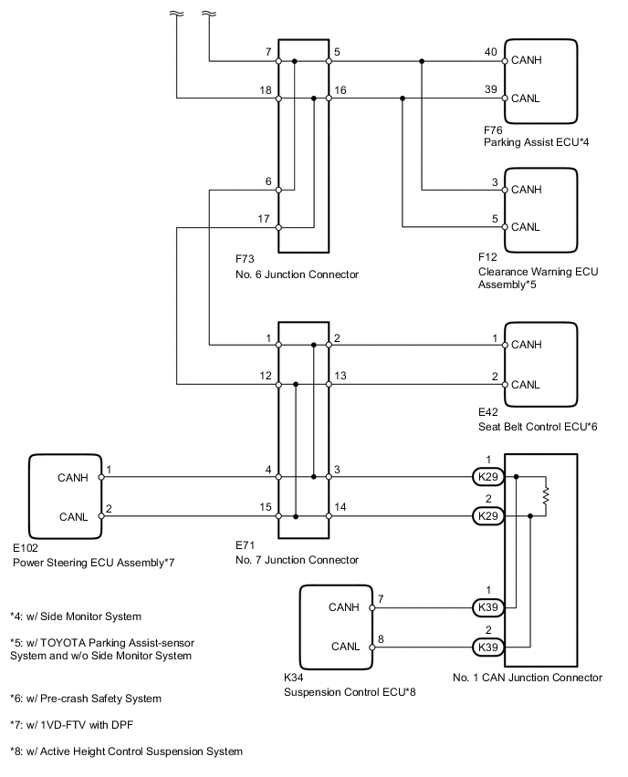
WIRING DIAGRAM
CAUTION / NOTICE / HINT
Tech Tips
Operating the ignition switch, any switches or any doors triggers related ECU and sensor communication with the CAN, which causes resistance variation.
PROCEDURE
-
PRECAUTION
Note
After turning the ignition switch off, waiting time may be required before disconnecting the cable from the battery terminal. Therefore, make sure to read the disconnecting the cable from the battery terminal notice before proceeding with work Click here.
NEXT 
-
DISCONNECT CABLE FROM NEGATIVE BATTERY TERMINAL
-
Disconnect the cable from the negative (-) battery terminal before measuring the resistances of the CAN main wire and the CAN branch wire.
CAUTION:
For vehicles with an SRS system:
Wait at least 90 seconds after disconnecting the cable from the negative (-) battery terminal to disable the SRS system.
Note
When disconnecting the cable, some systems need to be initialized after the cable is reconnected Click here.
NEXT
-
-
CHECK CAN BUS WIRE (CAN MAIN WIRE FOR DISCONNECTION, CHECK BUS LINE FOR SHORT CIRCUIT)
-
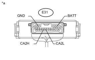
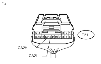
Text in Illustration *a Component with harness connected
(Network Gateway ECU)
Measure the resistance according to the value(s) in the table below.
Standard Resistance Tester Connection Switch Condition Specified Condition Resistance Malfunction E31-13 (CA2H) - E31-12 (CA2L) Ignition switch off 54 to 69 Ω Below 53 Ω: Short in line E31-13 (CA2H) - E31-12 (CA2L) Ignition switch off 54 to 69 Ω 70 Ω or higher: Open in CAN main bus line E31-13 (CA2H) - E31-2 (BATT) Ignition switch off 6 kΩ or higher Below 6 kΩ: +B short E31-12 (CA2L) - E31-2 (BATT) Ignition switch off 6 kΩ or higher Below 6 kΩ: +B short E31-13 (CA2H) - E31-4 (GND) Ignition switch off 200 Ω or higher Below 200 Ω: Ground short E31-12 (CA2L) - E31-4 (GND) Ignition switch off 200 Ω or higher Below 200 Ω: Ground short Result Result Proceed to NG
-
Open in CAN main wire
A NG
-
Short in line
-
+B short
-
Ground short
B OK C -
B 
CHECK FOR SHORT IN CAN BUS WIRES (NO. 7 JUNCTION CONNECTOR SIDE) Click here
C
CHECK HARNESS AND CONNECTOR (NETWORK GATEWAY ECU - BATTERY AND BODY GROUND) Click here
A
-
-
CHECK FOR OPEN IN MAIN BUS WIRE (NO. 7 CAN JUNCTION CONNECTOR - NETWORK GATEWAY ECU)
-
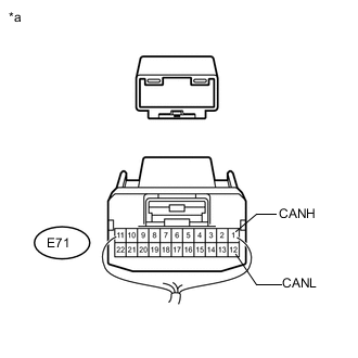
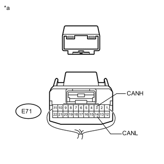
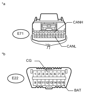
Text in Illustration *a Rear view of wire harness connector
(to No. 7 Junction Connector)
Disconnect the E71 No. 7 junction connector.
-
Measure the resistance according to the value(s) in the table below.
Standard Resistance Tester Connection Switch Condition Specified Condition E71-1 (CANH) - E71-12 (CANL) Ignition switch off 108 to 132 Ω
NG
CONNECT CONNECTOR Click here
OK
-
-
CHECK FOR OPEN IN CAN BUS MAIN WIRE (NO. 7 JUNCTION CONNECTOR - NO. 1 CAN JUNCTION CONNECTOR)
-
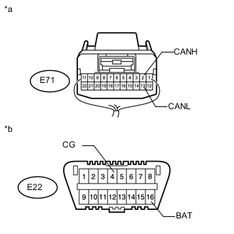
Text in Illustration *a Rear view of wire harness connector
(to No. 7 Junction Connector)
Measure the resistance according to the value(s) in the table below.
Standard Resistance Tester Connection Switch Condition Specified Condition E71-3 (CANH) - E71-14 (CANL) Ignition switch off 108 to 132 Ω
OK 
REPLACE NO. 7 JUNCTION CONNECTOR
NG
CONNECT CONNECTOR Click here
-
-
CONNECT CONNECTOR
-
Reconnect the E71 No. 7 junction connector.
NEXT
-
-
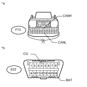
CHECK FOR OPEN IN CAN BUS MAIN WIRE (NO. 6 JUNCTION CONNECTOR - NO. 7 JUNCTION CONNECTOR)
-
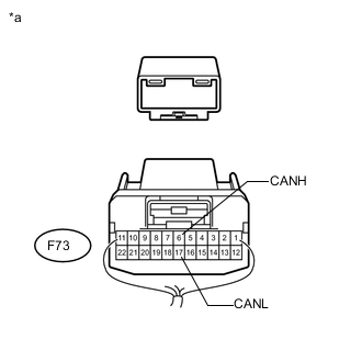
Text in Illustration *a Rear view of wire harness connector
(to No. 6 Junction Connector)
Disconnect the F73 No. 6 junction connector.
-
Measure the resistance according to the value(s) in the table below.
Standard Resistance Tester Connection Switch Condition Specified Condition F73-6 (CANH) - F73-17 (CANL) Ignition switch off 108 to 132 Ω
NG
REPAIR OR REPLACE CAN MAIN WIRE OR CONNECTOR (NO. 6 JUNCTION CONNECTOR - NO. 7 JUNCTION CONNECTOR)
OK
-
-
CHECK FOR OPEN IN CAN BUS MAIN WIRE (NO. 6 JUNCTION CONNECTOR - NETWORK GATEWAY ECU)
-
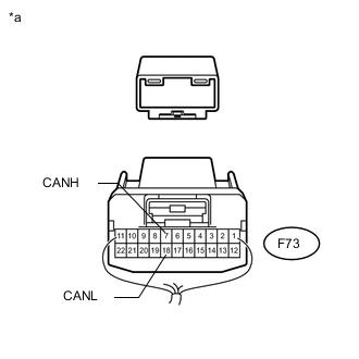
Text in Illustration *a Rear view of wire harness connector
(to No. 6 Junction Connector)
Measure the resistance according to the value(s) in the table below.
Standard Resistance Tester Connection Switch Condition Specified Condition F73-7 (CANH) - F73-18 (CANL) Ignition switch off 108 to 132 Ω
OK
REPLACE NO. 6 JUNCTION CONNECTOR
NG
-
-
CONNECT CONNECTOR
-
Reconnect the F73 No. 6 junction connector.
NEXT
-
-
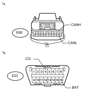
CHECK FOR OPEN IN CAN BUS MAIN WIRE (NO. 5 JUNCTION CONNECTOR - NO. 6 JUNCTION CONNECTOR)
-
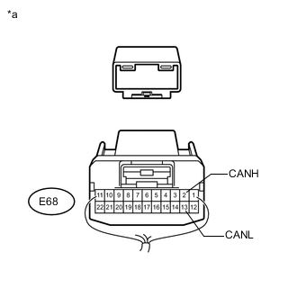
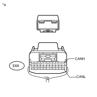
Text in Illustration *a Rear view of wire harness connector
(to No. 5 Junction Connector)
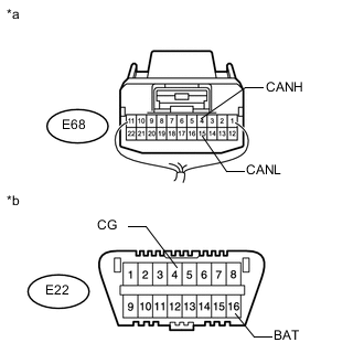
Disconnect the E68 No. 5 junction connector.
-
Measure the resistance according to the value(s) in the table below.
Standard Resistance Tester Connection Switch Condition Specified Condition E68-2 (CANH) - E68-13 (CANL) Ignition switch off 108 to 132 Ω
NG
REPAIR OR REPLACE CAN MAIN WIRE OR CONNECTOR (NO. 5 JUNCTION CONNECTOR - NO. 6 JUNCTION CONNECTOR)
OK
-
-
CHECK FOR OPEN IN CAN BUS MAIN WIRE (NO. 5 JUNCTION CONNECTOR - NETWORK GATEWAY ECU)
-
Text in Illustration *a Rear view of wire harness connector
(to No. 5 Junction Connector)
Measure the resistance according to the value(s) in the table below.
Standard Resistance Tester Connection Switch Condition Specified Condition E68-1 (CANH) - E68-12 (CANL) Ignition switch off 108 to 132 Ω
OK
REPLACE NO. 5 JUNCTION CONNECTOR
NG
-
-
CONNECT CONNECTOR
-
Reconnect the E68 No. 5 junction connector.
NEXT
-
-
CHECK FOR OPEN IN CAN BUS MAIN WIRE (NO. 4 JUNCTION CONNECTOR - NO. 5 JUNCTION CONNECTOR)
-
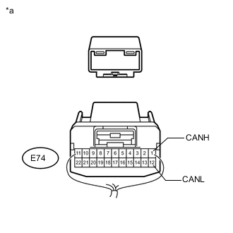
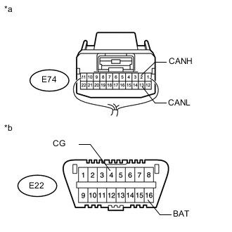
Text in Illustration *a Rear view of wire harness connector
(to No. 4 Junction Connector)
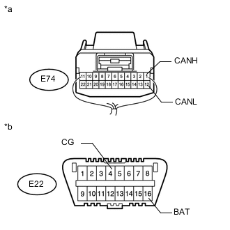
Disconnect the E74 No. 4 junction connector.
-
Measure the resistance according to the value(s) in the table below.
Standard Resistance Tester Connection Switch Condition Specified Condition E74-1 (CANH) - E74-12 (CANL) Ignition switch off 108 to 132 Ω
NG
REPAIR OR REPLACE CAN MAIN WIRE OR CONNECTOR (NO. 4 JUNCTION CONNECTOR - NO. 5 JUNCTION CONNECTOR)
OK
-
-
CHECK FOR OPEN IN CAN BUS MAIN WIRE (NO. 4 JUNCTION CONNECTOR - NETWORK GATEWAY ECU)
-
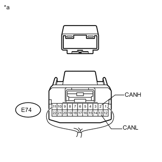
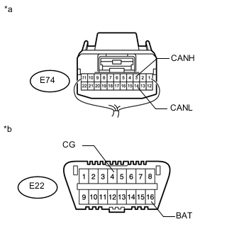
Text in Illustration *a Rear view of wire harness connector
(to No. 4 Junction Connector)
Measure the resistance according to the value(s) in the table below.
Standard Resistance Tester Connection Switch Condition Specified Condition E74-2 (CANH) - E74-13 (CANL) Ignition switch off 108 to 132 Ω
OK
REPLACE NO. 4 JUNCTION CONNECTOR
NG
CONNECT CONNECTOR Click here
-
-
CONNECT CONNECTOR
-
Reconnect the E71 No. 7 junction connector.
NEXT
-
-
CHECK FOR OPEN IN CAN BUS MAIN WIRE (NO. 1 CAN JUNCTION CONNECTOR - NO. 7 JUNCTION CONNECTOR)
-
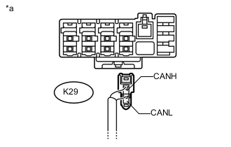
Text in Illustration *a Rear view of wire harness connector
(to No. 1 CAN Junction Connector)
Disconnect the K29 No. 1 CAN junction connector.
-
Measure the resistance according to the value(s) in the table below.
Standard Resistance Tester Connection Switch Condition Specified Condition K29-1 (CANH) - K29-2 (CANL) Ignition switch off 108 to 132 Ω
OK
REPLACE NO. 1 CAN JUNCTION CONNECTOR
NG
REPAIR OR REPLACE CAN MAIN WIRE OR CONNECTOR (NO. 1 CAN JUNCTION CONNECTOR - NO. 7 JUNCTION CONNECTOR)
-
-
CONNECT CONNECTOR
-
Reconnect the E74 No. 4 junction connector.
NEXT
-
-
CHECK FOR OPEN IN CAN BUS MAIN WIRE (NETWORK GATEWAY ECU - NO. 8 JUNCTION CONNECTOR)
-
Text in Illustration *a Rear view of wire harness connector
(to Network Gateway ECU)
Disconnect the E31 network gateway ECU connector.
-
Measure the resistance according to the value(s) in the table below.
Standard Resistance Tester Connection Switch Condition Specified Condition E31-13 (CA2H) - E31-12 (CA2L) Ignition switch off 108 to 132 Ω
OK
REPLACE NETWORK GATEWAY ECU Click here
NG
REPAIR OR REPLACE CAN MAIN WIRE CONNECTED TO NETWORK GATEWAY ECU (NETWORK GATEWAY ECU - NO. 4 JUNCTION CONNECTOR)
-
-
CHECK FOR SHORT IN CAN BUS WIRES (NO. 7 JUNCTION CONNECTOR SIDE)
-
Text in Illustration *a Component with harness connected
(Network Gateway ECU)
Disconnect the E71 No. 7 junction connector.
-
Measure the resistance according to the value(s) in the table below.
Standard Resistance Tester Connection Switch Condition Specified Condition E31-13 (CA2H) - E31-12 (CA2L) Ignition switch off 108 to 132 Ω E31-13 (CA2H) - E31-4 (GND) Ignition switch off 200 Ω or higher E31-12 (CA2L) - E31-4 (GND) Ignition switch off 200 Ω or higher E31-13 (CA2H) - E31-2 (BATT) Ignition switch off 6 kΩ or higher E31-12 (CA2L) - E31-2 (BATT) Ignition switch off 6 kΩ or higher Result Tester Connection Switch Condition OK (for 1VD-FTV with DPF) A OK (except 1VD-FTV with DPF) B NG C
B
CHECK FOR SHORT IN CAN BUS WIRES (NO. 7 JUNCTION CONNECTOR - SEAT BELT CONTROL ECU) Click here
C
CONNECT CONNECTOR Click here
A
-
-
CHECK FOR SHORT IN CAN BUS WIRES (NO. 7 JUNCTION CONNECTOR - POWER STEERING ECU ASSEMBLY)
-
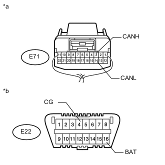
Text in Illustration *a Rear view of wire harness connector
(to No. 7 Junction Connector)
*b Front view of DLC3 Measure the resistance according to the value(s) in the table below.
Standard Resistance Tester Connection Switch Condition Specified Condition E71-4 (CANH) - E71-15 (CANL) Ignition switch off 200 Ω or higher E71-4 (CANH) - E22-4 (CG) Ignition switch off 200 Ω or higher E71-15 (CANL) - E22-4 (CG) Ignition switch off 200 Ω or higher E71-4 (CANH) - E22-16 (BAT) Ignition switch off 6 kΩ or higher E71-15 (CANL) - E22-16 (BAT) Ignition switch off 6 kΩ or higher
NG
CONNECT CONNECTOR Click here
OK
-
-
CHECK FOR SHORT IN CAN BUS WIRES (NO. 7 JUNCTION CONNECTOR - SEAT BELT CONTROL ECU)
Note
For vehicles without an pre-crash safety system, go to "Check for Short in CAN Bus Wires (No. 7 Junction Connector - No. 1 CAN Junction Connector)".
-
Text in Illustration *a Rear view of wire harness connector
(to No. 7 Junction Connector)
*b Front view of DLC3 Measure the resistance according to the value(s) in the table below.
Standard Resistance Tester Connection Switch Condition Specified Condition E71-2 (CANH) - E71-13 (CANL) Ignition switch off 200 Ω or higher E71-2 (CANH) - E22-4 (CG) Ignition switch off 200 Ω or higher E71-13 (CANL) - E22-4 (CG) Ignition switch off 200 Ω or higher E71-2 (CANH) - E22-16 (BAT) Ignition switch off 6 kΩ or higher E71-13 (CANL) - E22-16 (BAT) Ignition switch off 6 kΩ or higher
NG
CONNECT CONNECTOR Click here
OK
-
-
CHECK FOR SHORT IN CAN BUS WIRES (NO. 7 JUNCTION CONNECTOR - NO. 1 CAN JUNCTION CONNECTOR)
-
Text in Illustration *a Rear view of wire harness connector
(to No. 7 Junction Connector)
*b Front view of DLC3 Measure the resistance according to the value(s) in the table below.
Standard Resistance Tester Connection Switch Condition Specified Condition E71-3 (CANH) - E71-14 (CANL) Ignition switch off 108 to 132 Ω E71-3 (CANH) - E22-4 (CG) Ignition switch off 200 Ω or higher E71-14 (CANL) - E22-4 (CG) Ignition switch off 200 Ω or higher E71-3 (CANH) - E22-16 (BAT) Ignition switch off 6 kΩ or higher E71-14 (CANL) - E22-16 (BAT) Ignition switch off 6 kΩ or higher Result Tester Connection Switch Condition OK A NG (w/ Active Height Control Suspension) B NG (w/o Active Height Control Suspension) C
A
REPLACE NO. 7 JUNCTION CONNECTOR
B
CONNECT CONNECTOR Click here
C
CONNECT CONNECTOR Click here
-
-
CONNECT CONNECTOR
-
Reconnect the E71 No. 7 junction connector.
NEXT
-
-
CHECK FOR SHORT IN CAN BUS WIRES (NO. 6 JUNCTION CONNECTOR - NO. 7 JUNCTION CONNECTOR)
-
Text in Illustration *a Rear view of wire harness connector
(to No. 6 Junction Connector)
*b Front view of DLC3 Disconnect the F73 No. 6 junction connector.
-
Measure the resistance according to the value(s) in the table below.
Standard Resistance Tester Connection Switch Condition Specified Condition F73-6 (CANH) - F73-17 (CANL) Ignition switch off 108 to 132 Ω F73-6 (CANH) - E22-4 (CG) Ignition switch off 200 Ω or higher F73-17 (CANL) - E22-4 (CG) Ignition switch off 200 Ω or higher F73-6 (CANH) - E22-16 (BAT) Ignition switch off 6 kΩ or higher F73-17 (CANL) - E22-16 (BAT) Ignition switch off 6 kΩ or higher
NG
REPAIR OR REPLACE CAN MAIN WIRE OR CONNECTOR (NO. 6 JUNCTION CONNECTOR - NO. 7 JUNCTION CONNECTOR)
OK
-
-
CHECK FOR SHORT IN CAN BUS WIRES (NO. 6 JUNCTION CONNECTOR SIDE)
-
Text in Illustration *a Component with harness connected
(Network Gateway ECU)
Measure the resistance according to the value(s) in the table below.
Standard Resistance Tester Connection Switch Condition Specified Condition E31-13 (CA2H) - E31-12 (CA2L) Ignition switch off 108 to 132 Ω E31-13 (CA2H) - E31-4 (GND) Ignition switch off 200 Ω or higher E31-12 (CA2L) - E31-4 (GND) Ignition switch off 200 Ω or higher E31-13 (CA2H) - E31-2 (BATT) Ignition switch off 6 kΩ or higher E31-12 (CA2L) - E31-2 (BATT) Ignition switch off 6 kΩ or higher Result Result Proceed to OK (w/o TOYOTA Parking Assist-sensor System and w/o Side Monitor System) A OK (w/ TOYOTA Parking Assist-sensor System and w/o Side Monitor System) B OK (w/ Side Monitor System) C NG D
A
REPLACE NO. 6 JUNCTION CONNECTOR
C
CHECK FOR SHORT IN CAN BUS WIRES (NO. 6 JUNCTION CONNECTOR - PARKING ASSIST ECU) Click here
D
CONNECT CONNECTOR Click here
B
-
-
CHECK FOR SHORT IN CAN BUS WIRES (NO. 6 JUNCTION CONNECTOR - CLEARANCE WARNING ECU ASSEMBLY)
-
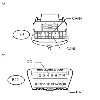
Text in Illustration *a Rear view of wire harness connector
(to No. 6 Junction Connector)
*b Front view of DLC3 Measure the resistance according to the value(s) in the table below.
Standard Resistance Tester Connection Switch Condition Specified Condition F73-5 (CANH) - F73-16 (CANL) Ignition switch off 200 Ω or higher F73-5 (CANH) - E22-4 (CG) Ignition switch off 200 Ω or higher F73-16 (CANL) - E22-4 (CG) Ignition switch off 200 Ω or higher F73-5 (CANH) - E22-16 (BAT) Ignition switch off 6 kΩ or higher F73-16 (CANL) - E22-16 (BAT) Ignition switch off 6 kΩ or higher
OK
REPLACE NO. 6 JUNCTION CONNECTOR
NG
CONNECT CONNECTOR Click here
-
-
CHECK FOR SHORT IN CAN BUS WIRES (NO. 6 JUNCTION CONNECTOR - PARKING ASSIST ECU)
-
Text in Illustration *a Rear view of wire harness connector
(to No. 6 Junction Connector)
*b Front view of DLC3 Measure the resistance according to the value(s) in the table below.
Standard Resistance Tester Connection Switch Condition Specified Condition F73-5 (CANH) - F73-16 (CANL) Ignition switch off 200 Ω or higher F73-5 (CANH) - E22-4 (CG) Ignition switch off 200 Ω or higher F73-16 (CANL) - E22-4 (CG) Ignition switch off 200 Ω or higher F73-5 (CANH) - E22-16 (BAT) Ignition switch off 6 kΩ or higher F73-16 (CANL) - E22-16 (BAT) Ignition switch off 6 kΩ or higher
OK
REPLACE NO. 6 JUNCTION CONNECTOR
NG
CONNECT CONNECTOR Click here
-
-
CONNECT CONNECTOR
-
Reconnect the F73 No. 6 junction connector.
NEXT
-
-
CHECK FOR SHORT IN CAN BUS WIRES (NO. 5 JUNCTION CONNECTOR - NO. 6 JUNCTION CONNECTOR)
-
Text in Illustration *a Rear view of wire harness connector
(to No. 5 Junction Connector)
*b Front view of DLC3 Disconnect the E68 No. 5 junction connector.
-
Measure the resistance according to the value(s) in the table below.
Standard Resistance Tester Connection Switch Condition Specified Condition E68-2 (CANH) - E68-13 (CANL) Ignition switch off 108 to 132 Ω E68-2 (CANH) - E22-4 (CG) Ignition switch off 200 Ω or higher E68-13 (CANL) - E22-4 (CG) Ignition switch off 200 Ω or higher E68-2 (CANH) - E22-16 (BAT) Ignition switch off 6 kΩ or higher E68-13 (CANL) - E22-16 (BAT) Ignition switch off 6 kΩ or higher
NG
REPAIR OR REPLACE CAN MAIN WIRE OR CONNECTOR (NO. 5 JUNCTION CONNECTOR - NO. 6 JUNCTION CONNECTOR)
OK
-
-
CHECK FOR SHORT IN CAN BUS WIRES (NO. 5 JUNCTION CONNECTOR SIDE)
-
Text in Illustration *a Component with harness connected
(Network Gateway ECU)
Measure the resistance according to the value(s) in the table below.
Standard Resistance Tester Connection Switch Condition Specified Condition E31-13 (CA2H) - E31-12 (CA2L) Ignition switch off 108 to 132 Ω E31-13 (CA2H) - E31-4 (GND) Ignition switch off 200 Ω or higher E31-12 (CA2L) - E31-4 (GND) Ignition switch off 200 Ω or higher E31-13 (CA2H) - E31-2 (BATT) Ignition switch off 6 kΩ or higher E31-12 (CA2L) - E31-2 (BATT) Ignition switch off 6 kΩ or higher
NG
CONNECT CONNECTOR Click here
OK
-
-
CHECK FOR SHORT IN CAN BUS WIRES (NO. 5 JUNCTION CONNECTOR - YAW RATE SENSOR ASSEMBLY)
Note
For vehicles without an vehicle stability control system, go to "Check for Short in CAN Bus Wires (No. 5 Junction Connector - Distance Control ECU Assembly)".
-
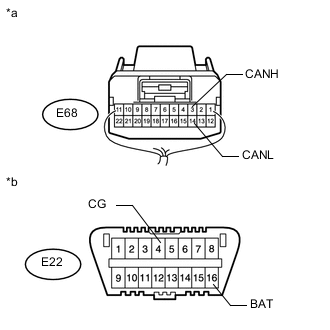
Text in Illustration *a Rear view of wire harness connector
(to No. 5 Junction Connector)
*b Front view of DLC3 Measure the resistance according to the value(s) in the table below.
Standard Resistance Tester Connection Switch Condition Specified Condition E68-3 (CANH) - E68-14 (CANL) Ignition switch off 200 Ω or higher E68-3 (CANH) - E22-4 (CG) Ignition switch off 200 Ω or higher E68-14 (CANL) - E22-4 (CG) Ignition switch off 200 Ω or higher E68-3 (CANH) - E22-16 (BAT) Ignition switch off 6 kΩ or higher E68-14 (CANL) - E22-16 (BAT) Ignition switch off 6 kΩ or higher
NG
CONNECT CONNECTOR Click here
OK
-
-
CHECK FOR SHORT IN CAN BUS WIRES (NO. 5 JUNCTION CONNECTOR - DISTANCE CONTROL ECU ASSEMBLY)
Note
For vehicles without an dynamic radar cruise control system, replace No. 5 junction connector..
-
Text in Illustration *a Rear view of wire harness connector
(to No. 5 Junction Connector)
*b Front view of DLC3 Measure the resistance according to the value(s) in the table below.
Standard Resistance Tester Connection Switch Condition Specified Condition E68-4 (CANH) - E68-15 (CANL) Ignition switch off 200 Ω or higher E68-4 (CANH) - E22-4 (CG) Ignition switch off 200 Ω or higher E68-15 (CANL) - E22-4 (CG) Ignition switch off 200 Ω or higher E68-4 (CANH) - E22-16 (BAT) Ignition switch off 6 kΩ or higher E68-15 (CANL) - E22-16 (BAT) Ignition switch off 6 kΩ or higher
OK
REPLACE NO. 5 JUNCTION CONNECTOR
NG
CONNECT CONNECTOR Click here
-
-
CONNECT CONNECTOR
-
Reconnect the E68 No. 5 junction connector.
NEXT
-
-
CHECK FOR SHORT IN CAN BUS WIRES (NO. 4 JUNCTION CONNECTOR - NO. 5 JUNCTION CONNECTOR)
-
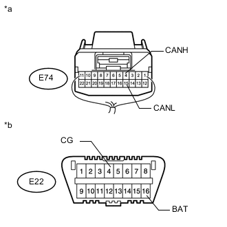
Text in Illustration *a Rear view of wire harness connector
(to No. 4 Junction Connector)
*b Front view of DLC3 Disconnect the E74 No. 4 junction connector.
-
Measure the resistance according to the value(s) in the table below.
Standard Resistance Tester Connection Switch Condition Specified Condition E74-1 (CANH) - E74-12 (CANL) Ignition switch off 108 to 132 Ω E74-1 (CANH) - E22-4 (CG) Ignition switch off 200 Ω or higher E74-12 (CANL) - E22-4 (CG) Ignition switch off 200 Ω or higher E74-1 (CANH) - E22-16 (BAT) Ignition switch off 6 kΩ or higher E74-12 (CANL) - E22-16 (BAT) Ignition switch off 6 kΩ or higher
NG
REPAIR OR REPLACE CAN MAIN WIRE OR CONNECTOR (NO. 4 JUNCTION CONNECTOR - NO. 5 JUNCTION CONNECTOR)
OK
-
-
CHECK FOR SHORT IN CAN BUS WIRES (NO. 4 JUNCTION CONNECTOR - 4WD CONTROL ECU)
-

Text in Illustration *a Rear view of wire harness connector
(to No. 4 Junction Connector)
*b Front view of DLC3 Measure the resistance according to the value(s) in the table below.
Standard Resistance Tester Connection Switch Condition Specified Condition E74-6 (CANH) - E74-17 (CANL) Ignition switch off 200 Ω or higher E74-6 (CANH) - E22-4 (CG) Ignition switch off 200 Ω or higher E74-17 (CANL) - E22-4 (CG) Ignition switch off 200 Ω or higher E74-6 (CANH) - E22-16 (BAT) Ignition switch off 6 kΩ or higher E74-17 (CANL) - E22-16 (BAT) Ignition switch off 6 kΩ or higher
NG
CONNECT CONNECTOR Click here
OK
-
-
CHECK FOR SHORT IN CAN BUS WIRES (NO. 4 JUNCTION CONNECTOR - STEERING CONTROL ECU)
Note
For vehicles without an variable gear ratio steering system, go to "Check for Short in CAN Bus Wires (No. 4 Junction Connector - Steering Angle Sensor)".
-
Text in Illustration *a Rear view of wire harness connector
(to No. 4 Junction Connector)
*b Front view of DLC3 Measure the resistance according to the value(s) in the table below.
Standard Resistance Tester Connection Switch Condition Specified Condition E74-3 (CANH) - E74-14 (CANL) Ignition switch off 200 Ω or higher E74-3 (CANH) - E22-4 (CG) Ignition switch off 200 Ω or higher E74-14 (CANL) - E22-4 (CG) Ignition switch off 200 Ω or higher E74-3 (CANH) - E22-16 (BAT) Ignition switch off 6 kΩ or higher E74-14 (CANL) - E22-16 (BAT) Ignition switch off 6 kΩ or higher
NG
CONNECT CONNECTOR Click here
OK
-
-
CHECK FOR SHORT IN CAN BUS WIRES (NO. 4 JUNCTION CONNECTOR - STEERING ANGLE SENSOR)
Note
For vehicles without an vehicle stability control system, go to "Check for Short in CAN Bus Wires (No. 4 Junction Connector - Skid Control ECU)".
-
Text in Illustration *a Rear view of wire harness connector
(to No. 4 Junction Connector)
*b Front view of DLC3 Measure the resistance according to the value(s) in the table below.
Standard Resistance Tester Connection Switch Condition Specified Condition E74-4 (CANH) - E74-15 (CANL) Ignition switch off 200 Ω or higher E74-4 (CANH) - E22-4 (CG) Ignition switch off 200 Ω or higher E74-15 (CANL) - E22-4 (CG) Ignition switch off 200 Ω or higher E74-4 (CANH) - E22-16 (BAT) Ignition switch off 6 kΩ or higher E74-15 (CANL) - E22-16 (BAT) Ignition switch off 6 kΩ or higher
NG
CONNECT CONNECTOR Click here
OK
-
-
CHECK FOR SHORT IN CAN BUS WIRES (NO. 4 JUNCTION CONNECTOR - SKID CONTROL ECU)
-

Text in Illustration *a Rear view of wire harness connector
(to No. 4 Junction Connector)
*b Front view of DLC3 Measure the resistance according to the value(s) in the table below.
Standard Resistance Tester Connection Switch Condition Specified Condition E74-5 (CANH) - E74-16 (CANL) Ignition switch off 200 Ω or higher E74-5 (CANH) - E22-4 (CG) Ignition switch off 200 Ω or higher E74-16 (CANL) - E22-4 (CG) Ignition switch off 200 Ω or higher E74-5 (CANH) - E22-16 (BAT) Ignition switch off 6 kΩ or higher E74-16 (CANL) - E22-16 (BAT) Ignition switch off 6 kΩ or higher
NG
CONNECT CONNECTOR Click here
OK
-
-
CHECK FOR SHORT IN CAN BUS WIRES (NO. 4 JUNCTION CONNECTOR - NETWORK GATEWAY ECU)
-
Text in Illustration *a Rear view of wire harness connector
(to No. 4 Junction Connector)
*b Front view of DLC3 Measure the resistance according to the value(s) in the table below.
Standard Resistance Tester Connection Switch Condition Specified Condition E74-2 (CANH) - E74-13 (CANL) Ignition switch off 108 to 132 Ω E74-2 (CANH) - E22-4 (CG) Ignition switch off 200 Ω or higher E74-13 (CANL) - E22-4 (CG) Ignition switch off 200 Ω or higher E74-2 (CANH) - E22-16 (BAT) Ignition switch off 6 kΩ or higher E74-13 (CANL) - E22-16 (BAT) Ignition switch off 6 kΩ or higher
OK
REPLACE NO. 4 JUNCTION CONNECTOR
NG
CONNECT CONNECTOR Click here
-
-
CONNECT CONNECTOR
-
Reconnect the E71 No. 7 junction connector.
NEXT
-
-
CHECK FOR SHORT IN CAN BUS WIRES (POWER STEERING ECU ASSEMBLY)
-
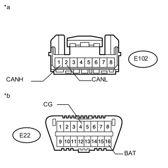
Text in Illustration *a Front view of wire harness connector
(to Power Steering ECU Assembly)
*b Front view of DLC3 Disconnect the E102 power steering ECU assembly connector.
-
Measure the resistance according to the value(s) in the table below.
Standard Resistance Tester Connection Switch Condition Specified Condition E102-1 (CANH) - E102-2 (CANL) Ignition switch off 54 to 69 Ω E102-1 (CANH) - E22-4 (CG) Ignition switch off 200 Ω or higher E102-2 (CANL) - E22-4 (CG) Ignition switch off 200 Ω or higher E102-1 (CANH) - E22-16 (BAT) Ignition switch off 6 kΩ or higher E102-2 (CANL) - E22-16 (BAT) Ignition switch off 6 kΩ or higher
OK
REPLACE POWER STEERING ECU ASSEMBLY Click here
NG
REPAIR OR REPLACE CAN BRANCH WIRE CONNECTED TO POWER STEERING ECU ASSEMBLY (CANH, CANL)
-
-
CONNECT CONNECTOR
-
Reconnect the E71 No. 7 junction connector.
NEXT
-
-
CHECK FOR SHORT IN CAN BUS WIRES (SEAT BELT CONTROL ECU)
-
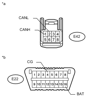
Text in Illustration *a Front view of wire harness connector
(to Seat Belt Control ECU)
*b Front view of DLC3 Disconnect the E42 seat belt control ECU connector.
-
Measure the resistance according to the value(s) in the table below.
Standard Resistance Tester Connection Switch Condition Specified Condition E42-1 (CANH) - E42-2 (CANL) Ignition switch off 54 to 69 Ω E42-1 (CANH) - E22-4 (CG) Ignition switch off 200 Ω or higher E42-2 (CANL) - E22-4 (CG) Ignition switch off 200 Ω or higher E42-1 (CANH) - E22-16 (BAT) Ignition switch off 6 kΩ or higher E42-2 (CANL) - E22-16 (BAT) Ignition switch off 6 kΩ or higher
OK
REPLACE SEAT BELT CONTROL ECU Click here
NG
REPAIR OR REPLACE CAN BRANCH WIRE CONNECTED TO SEAT BELT CONTROL ECU (CANH, CANL)
-
-
CONNECT CONNECTOR
-
Reconnect the E71 No. 7 junction connector.
NEXT
-
-
CHECK FOR SHORT IN CAN BUS WIRES (NO. 1 CAN JUNCTION CONNECTOR - SUSPENSION CONTROL ECU)
-
Text in Illustration *a Rear view of wire harness connector
(to No. 1 CAN Junction Connector)
*b Front view of DLC3 Disconnect the K39 No. 1 CAN junction connector.
-
Measure the resistance according to the value(s) in the table below.
Standard Resistance Tester Connection Switch Condition Specified Condition K39-1 (CANH) - K39-2 (CANL) Ignition switch off 200 Ω or higher K39-1 (CANH) - E22-4 (CG) Ignition switch off 200 Ω or higher K39-2 (CANL) - E22-4 (CG) Ignition switch off 200 Ω or higher K39-1 (CANH) - E22-16 (BAT) Ignition switch off 6 kΩ or higher K39-2 (CANL) - E22-16 (BAT) Ignition switch off 6 kΩ or higher
NG
CONNECT CONNECTOR Click here
OK
-
-
CHECK FOR SHORT IN CAN BUS WIRES (NO. 1 CAN JUNCTION CONNECTOR)
-
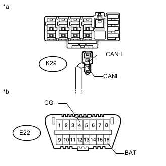
Text in Illustration *a Rear view of wire harness connector
(to No. 1 CAN Junction Connector)
*b Front view of DLC3 Disconnect the K29 No. 1 CAN junction connector.
-
Measure the resistance according to the value(s) in the table below.
Standard Resistance Tester Connection Switch Condition Specified Condition K29-1 (CANH) - K29-2 (CANL) Ignition switch off 108 to 132 Ω K29-1 (CANH) - E22-4 (CG) Ignition switch off 200 Ω or higher K29-2 (CANL) - E22-4 (CG) Ignition switch off 200 Ω or higher K29-1 (CANH) - E22-16 (BAT) Ignition switch off 6 kΩ or higher K29-2 (CANL) - E22-16 (BAT) Ignition switch off 6 kΩ or higher
OK
REPLACE NO. 1 CAN JUNCTION CONNECTOR
NG
REPAIR OR REPLACE CAN MAIN WIRE OR CONNECTOR (NO. 1 CAN JUNCTION CONNECTOR - NO. 7 JUNCTION CONNECTOR)
-
-
CONNECT CONNECTOR
-
Reconnect the K39 No. 1 CAN junction connector.
NEXT
-
-
CHECK FOR SHORT IN CAN BUS WIRES (SUSPENSION CONTROL ECU)
-
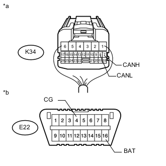
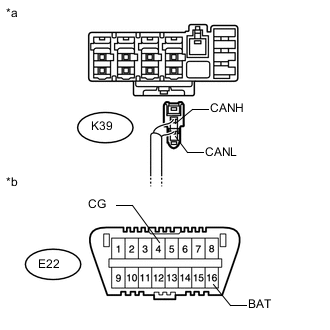
Text in Illustration *a Rear view of wire harness connector
(to Suspension Control ECU)
*b Front view of DLC3 Disconnect the K34 suspension control ECU connector.
-
Measure the resistance according to the value(s) in the table below.
Standard Resistance Tester Connection Switch Condition Specified Condition K34-7 (CANH) - K34-8 (CANL) Ignition switch off 54 to 69 Ω K34-7 (CANH) - E22-4 (CG) Ignition switch off 200 Ω or higher K34-8 (CANL) - E22-4 (CG) Ignition switch off 200 Ω or higher K34-7 (CANH) - E22-16 (BAT) Ignition switch off 6 kΩ or higher K34-8 (CANL) - E22-16 (BAT) Ignition switch off 6 kΩ or higher
OK
REPLACE SUSPENSION CONTROL ECU Click here
NG
REPAIR OR REPLACE CAN BRANCH WIRE CONNECTED TO SUSPENSION CONTROL ECU (CANH, CANL)
-
-
CONNECT CONNECTOR
-
Reconnect the E74 No. 7 junction connector.
NEXT
-
-
CHECK FOR SHORT IN CAN BUS WIRES (NO. 1 CAN JUNCTION CONNECTOR)
-
Text in Illustration *a Rear view of wire harness connector
(to No. 1 CAN Junction Connector)
*b Front view of DLC3 Disconnect the K29 No. 1 CAN junction connector.
-
Measure the resistance according to the value(s) in the table below.
Standard Resistance Tester Connection Switch Condition Specified Condition K29-1 (CANH) - K29-2 (CANL) Ignition switch off 108 to 132 Ω K29-1 (CANH) - E22-4 (CG) Ignition switch off 200 Ω or higher K29-2 (CANL) - E22-4 (CG) Ignition switch off 200 Ω or higher K29-1 (CANH) - E22-16 (BAT) Ignition switch off 6 kΩ or higher K29-2 (CANL) - E22-16 (BAT) Ignition switch off 6 kΩ or higher
OK
REPLACE NO. 1 CAN JUNCTION CONNECTOR
NG
REPAIR OR REPLACE CAN MAIN WIRE OR CONNECTOR (NO. 1 CAN JUNCTION CONNECTOR - NO. 7 JUNCTION CONNECTOR)
-
-
CONNECT CONNECTOR
-
Reconnect the F73 No. 6 junction connector.
NEXT
-
-
CHECK FOR SHORT IN CAN BUS WIRES (CLEARANCE WARNING ECU ASSEMBLY)
-
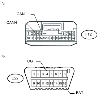
Text in Illustration *a Front view of wire harness connector
(to Clearance Warning ECU Assembly)
*b Front view of DLC3 Disconnect the F12 clearance warning ECU assembly connector.
-
Measure the resistance according to the value(s) in the table below.
Standard Resistance Tester Connection Switch Condition Specified Condition F12-3 (CANH) - F12-5 (CANL) Ignition switch off 54 to 69 Ω F12-3 (CANH) - E22-4 (CG) Ignition switch off 200 Ω or higher F12-5 (CANL) - E22-4 (CG) Ignition switch off 200 Ω or higher F12-3 (CANH) - E22-16 (BAT) Ignition switch off 6 kΩ or higher F12-5 (CANL) - E22-16 (BAT) Ignition switch off 6 kΩ or higher
OK
REPLACE CLEARANCE WARNING ECU ASSEMBLY Click here
NG
REPAIR OR REPLACE CAN BRANCH WIRE CONNECTED TO CLEARANCE WARNING ECU ASSEMBLY (CANH, CANL)
-
-
CONNECT CONNECTOR
-
Reconnect the F73 No. 6 junction connector.
NEXT
-
-
CHECK FOR SHORT IN CAN BUS WIRES (PARKING ASSIST ECU)
-
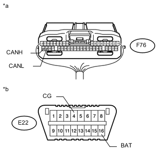
Text in Illustration *a Rear view of wire harness connector
(to Parking Assist ECU)
*b Front view of DLC3 Disconnect the F76 parking assist ECU connector.
-
Measure the resistance according to the value(s) in the table below.
Standard Resistance Tester Connection Switch Condition Specified Condition F76-40 (CANH) - F76-39 (CANL) Ignition switch off 54 to 69 Ω F76-40 (CANH) - E22-4 (CG) Ignition switch off 200 Ω or higher F76-39 (CANL) - E22-4 (CG) Ignition switch off 200 Ω or higher F76-40 (CANH) - E22-16 (BAT) Ignition switch off 6 kΩ or higher F76-39 (CANL) - E22-16 (BAT) Ignition switch off 6 kΩ or higher
OK
REPLACE PARKING ASSIST ECU Click here
NG
REPAIR OR REPLACE CAN BRANCH WIRE CONNECTED TO PARKING ASSIST ECU (CANH, CANL)
-
-
CONNECT CONNECTOR
-
Reconnect the E68 No. 5 junction connector.
NEXT
-
-
CHECK FOR SHORT IN CAN BUS WIRES (YAW RATE SENSOR ASSEMBLY)
-
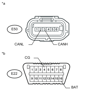
Text in Illustration *a Front view of wire harness connector
(to Yaw Rate Sensor Assembly)
*b Front view of DLC3 Disconnect the E50 yaw rate sensor assembly connector.
-
Measure the resistance according to the value(s) in the table below.
Standard Resistance Tester Connection Switch Condition Specified Condition E50-3 (CANH) - E50-2 (CANL) Ignition switch off 54 to 69 Ω E50-3 (CANH) - E22-4 (CG) Ignition switch off 200 Ω or higher E50-2 (CANL) - E22-4 (CG) Ignition switch off 200 Ω or higher E50-3 (CANH) - E22-16 (BAT) Ignition switch off 6 kΩ or higher E50-2 (CANL) - E22-16 (BAT) Ignition switch off 6 kΩ or higher
OK
REPLACE YAW RATE SENSOR ASSEMBLY Click here
NG
REPAIR OR REPLACE CAN BRANCH WIRE CONNECTED TO YAW RATE SENSOR ASSEMBLY (CANH, CANL)
-
-
CONNECT CONNECTOR
-
Reconnect the E68 No. 5 junction connector.
NEXT
-
-
CHECK FOR SHORT IN CAN BUS WIRES (DISTANCE CONTROL ECU ASSEMBLY)
-
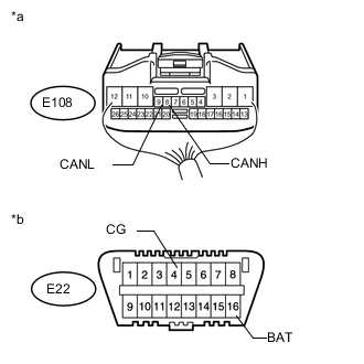
Text in Illustration *a Rear view of wire harness connector
(to Distance Control ECU Assembly)
*b Front view of DLC3 Disconnect the E108 distance control ECU assembly connector.
-
Measure the resistance according to the value(s) in the table below.
Standard Resistance Tester Connection Switch Condition Specified Condition E108-8 (CANH) - E108-9 (CANL) Ignition switch off 54 to 69 Ω E108-8 (CANH) - E22-4 (CG) Ignition switch off 200 Ω or higher E108-9 (CANL) - E22-4 (CG) Ignition switch off 200 Ω or higher E108-8 (CANH) - E22-16 (BAT) Ignition switch off 6 kΩ or higher E108-9 (CANL) - E22-16 (BAT) Ignition switch off 6 kΩ or higher
OK
REPLACE DISTANCE CONTROL ECU ASSEMBLY Click here
NG
REPAIR OR REPLACE CAN BRANCH WIRE CONNECTED TO DISTANCE CONTROL ECU ASSEMBLY (CANH, CANL)
-
-
CONNECT CONNECTOR
-
Reconnect the E74 No. 4 junction connector.
NEXT
-
-
CHECK FOR SHORT IN CAN BUS WIRES (4WD CONTROL ECU)
-
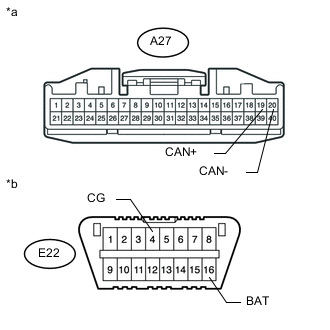
Text in Illustration *a Front view of wire harness connector
(to 4WD Control ECU)
*b Front view of DLC3 Disconnect the A27 4WD control ECU connector.
-
Measure the resistance according to the value(s) in the table below.
Standard Resistance Tester Connection Switch Condition Specified Condition A27-19 (CAN+) - A29-20 (CAN-) Ignition switch off 54 to 69 Ω A27-19 (CAN+) - E22-4 (CG) Ignition switch off 200 Ω or higher A29-20 (CAN-) - E22-4 (CG) Ignition switch off 200 Ω or higher A27-19 (CAN+) - E22-16 (BAT) Ignition switch off 6 kΩ or higher A29-20 (CAN-) - E22-16 (BAT) Ignition switch off 6 kΩ or higher
OK
REPLACE 4WD CONTROL ECU Click here
NG
REPAIR OR REPLACE CAN BRANCH WIRE CONNECTED TO 4WD CONTROL ECU (CAN+, CAN-)
-
-
CONNECT CONNECTOR
-
Reconnect the E74 No. 4 junction connector.
NEXT
-
-
CHECK FOR SHORT IN CAN BUS WIRES (STEERING CONTROL ECU)
-
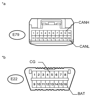
Text in Illustration *a Front view of wire harness connector
(to Steering Control ECU)
*b Front view of DLC3 Disconnect the E79 suspension control ECU connector.
-
Measure the resistance according to the value(s) in the table below.
Standard Resistance Tester Connection Switch Condition Specified Condition E79-9 (CANH) - E79-20 (CANL) Ignition switch off 54 to 69 Ω E79-9 (CANH) - E22-4 (CG) Ignition switch off 200 Ω or higher E79-20 (CANL) - E22-4 (CG) Ignition switch off 200 Ω or higher E79-9 (CANH) - E22-16 (BAT) Ignition switch off 6 kΩ or higher E79-20 (CANL) - E22-16 (BAT) Ignition switch off 6 kΩ or higher
OK
REPLACE STEERING CONTROL ECU Click here
NG
REPAIR OR REPLACE CAN BRANCH WIRE CONNECTED TO STEERING CONTROL ECU (CANH, CANL)
-
-
CONNECT CONNECTOR
-
Reconnect the E74 No. 4 junction connector.
NEXT
-
-
CHECK FOR SHORT IN CAN BUS WIRES (STEERING ANGLE SENSOR)
-
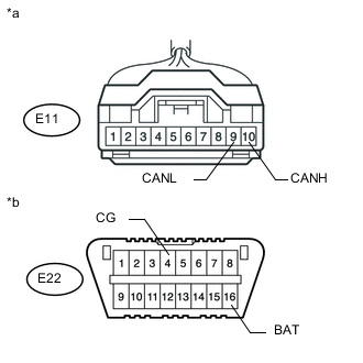
Text in Illustration *a Front view of wire harness connector
(to Steering Angle Sensor)
*b Front view of DLC3 Disconnect the E11 steering angle sensor connector.
-
Measure the resistance according to the value(s) in the table below.
Standard Resistance Tester Connection Switch Condition Specified Condition E11-10 (CANH) - E11-9 (CANL) Ignition switch off 54 to 69 Ω E11-10 (CANH) - E22-4 (CG) Ignition switch off 200 Ω or higher E11-9 (CANL) - E22-4 (CG) Ignition switch off 200 Ω or higher E11-10 (CANH) - E22-16 (BAT) Ignition switch off 6 kΩ or higher E11-9 (CANL) - E22-16 (BAT) Ignition switch off 6 kΩ or higher
OK
REPLACE STEERING ANGLE SENSOR Click here
NG
REPAIR OR REPLACE CAN BRANCH WIRE CONNECTED TO STEERING ANGLE SENSOR (CAMH, CANL)
-
-
CONNECT CONNECTOR
-
Reconnect the E74 No. 4 junction connector.
NEXT
-
-
CHECK FOR SHORT IN CAN BUS WIRES (SKID CONTROL ECU)
-
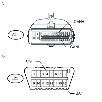
Text in Illustration *a Front view of wire harness connector
(to Master Cylinder Solenoid [Skid Control ECU])
*b Front view of DLC3 Disconnect the A24 master cylinder solenoid (skid control ECU) connector.
-
Measure the resistance according to the value(s) in the table below.
Standard Resistance Tester Connection Switch Condition Specified Condition A24-11 (CANH) - A24-25 (CANL) Ignition switch off 54 to 69 Ω A24-11 (CANH) - E22-4 (CG) Ignition switch off 200 Ω or higher A24-25 (CANL) - E22-4 (CG) Ignition switch off 200 Ω or higher A24-11 (CANH) - E22-16 (BAT) Ignition switch off 6 kΩ or higher A24-25 (CANL) - E22-16 (BAT) Ignition switch off 6 kΩ or higher
OK
REPLACE MASTER CYLINDER SOLENOID (SKID CONTROL ECU) Click here
NG
REPAIR OR REPLACE CAN BRANCH WIRE CONNECTED TO SKID CONTROL ECU (CANH, CANL)
-
-
CONNECT CONNECTOR
-
Reconnect the E74 No. 4 junction connector.
NEXT
-
-
CHECK FOR SHORT IN CAN BUS WIRES (NETWORK GATEWAY ECU)
-
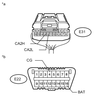
Text in Illustration *a Rear view of wire harness connector
(to Network Gateway ECU)
*b Front view of DLC3 Disconnect the E31 network gateway ECU connector.
-
Measure the resistance according to the value(s) in the table below.
Standard Resistance Tester Connection Switch Condition Specified Condition E31-13 (CA2H) - E31-12 (CA2L) Ignition switch off 54 to 69 Ω E31-13 (CA2H) - E22-4 (CG) Ignition switch off 200 Ω or higher E31-12 (CA2L) - E22-4 (CG) Ignition switch off 200 Ω or higher E31-13 (CA2H) - E22-16 (BAT) Ignition switch off 6 kΩ or higher E31-12 (CA2L) - E22-16 (BAT) Ignition switch off 6 kΩ or higher
OK
REPLACE NETWORK GATEWAY ECU Click here
NG
REPAIR OR REPLACE CAN MAIN WIRE CONNECTED TO NETWORK GATEWAY ECU (CA2H, CA2L)
-
-
CHECK HARNESS AND CONNECTOR (NETWORK GATEWAY ECU - BATTERY AND BODY GROUND)
-
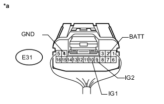
Text in Illustration *a Rear view of wire harness connector
(to Network Gateway ECU)
Connect the cable to the negative (-) battery terminal.
Note
When disconnecting the cable, some systems need to be initialized after the cable is reconnected Click here.
-
Disconnect the E31 network gateway ECU connector.
-
Measure the resistance according to the value(s) in the table below.
Standard Resistance Tester Connection Condition Specified Condition E31-4 (GND) - Body ground Always Below 1 Ω -
Measure the voltage according to the value(s) in the table below.
Standard Voltage Tester Connection Switch Condition Specified Condition E31-2 (BATT) - Body ground Always 11 to 14 V E31-9 (IG2) - Body ground Ignition switch ON 11 to 14 V E31-10 (IG1) - Body ground Ignition switch ON 11 to 14 V
OK
REPLACE NETWORK GATEWAY ECU Click here
NG
REPAIR OR REPLACE HARNESS OR CONNECTOR
-