CAN COMMUNICATION SYSTEM(for LHD), Diagnostic DTC:U1002 (CAN MS BUS)
| DTC Code | DTC Name |
|---|---|
| U1002 (CAN MS BUS) | Lost Communication with Gateway Module (Main body ECU) |
DESCRIPTION
-
The main body ECU stores this DTC when no signals can be received from the ECUs that have been memorized as those connected to the CAN MS bus.
-
When the main body ECU receives a response signal from the ECUs connected to the CAN MS bus, the main body ECU recognizes and memorizes that the ECU is connected to the CAN MS bus. Based on this memorized data, the main body ECU monitors for malfunctions in the ECUs connected to the CAN MS bus when communicating with those ECUs. If the main body ECU cannot receive response signals from the ECUs that have been memorized as those connected to the CAN MS bus, the main body ECU determines that a malfunction exists.
-
If 2 or more DTCs are output during the DTC check, one side of the CAN branch wire may be open (one side of the CANH [CAN branch wire]/CANL [CAN branch wire] of the ECU and/or sensor is open).
| DTC Code | DTC Detection Condition | Trouble Area |
|---|---|---|
| U1002 (CAN MS BUS) | Lost communication with the gateway module (main body ECU). |
|
-
*1: w/ Rain Sensor
-
*2: w/ Seat Memory
-
*3: w/ Power Tilt Power Telescopic Steering Column System
-
*4: w/ Entry and Start System
-
*5: w/ Power Back Door System
-
*6: w/ Tire Pressure Warning System
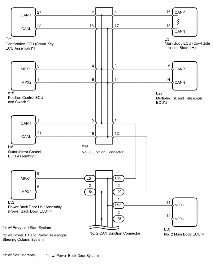
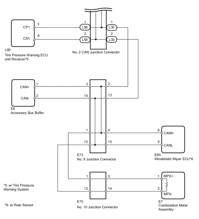
WIRING DIAGRAM
CAUTION / NOTICE / HINT
Tech Tips
Operating the ignition switch, any switches or any doors triggers related ECU and sensor communication with the CAN, which causes resistance variation.
PROCEDURE
-
PRECAUTION
Note
After turning the ignition switch off, waiting time may be required before disconnecting the cable from the battery terminal. Therefore, make sure to read the disconnecting the cable from the battery terminal notice before proceeding with work Click here.
NEXT 
-
DISCONNECT CABLE FROM NEGATIVE BATTERY TERMINAL
-
Disconnect the cable from the negative (-) battery terminal before measuring the resistances of the CAN main wire and the CAN branch wire.
CAUTION:
For vehicles with an SRS system:
Wait at least 90 seconds after disconnecting the cable from the negative (-) battery terminal to disable the SRS system.
Note
When disconnecting the cable, some systems need to be initialized after the cable is reconnected Click here.
NEXT
-
-
CHECK CAN BUS WIRE (CAN MAIN WIRE FOR DISCONNECTION, CHECK BUS LINE FOR SHORT CIRCUIT)
-
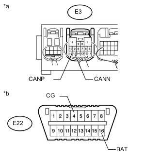
Text in Illustration *a Component with harness connected
(Main Body ECU [Cowl Side Junction Block LH])
*b Front view of DLC3 Measure the resistance according to the value(s) in the table below.
Standard Resistance Tester Connection Switch Condition Specified Condition Resistance Malfunction E3-16 (CANP) - E3-15 (CANN) Ignition switch off 54 to 69 Ω Below 53 Ω: Short in line E3-16 (CANP) - E3-15 (CANN) Ignition switch off 54 to 69 Ω 70 Ω or higher: Open in CAN main bus line E3-16 (CANP) - E22-16 (BAT) Ignition switch off 6 kΩ or higher Below 6 kΩ: +B short E3-15 (CANN) - E22-16 (BAT) Ignition switch off 6 kΩ or higher Below 6 kΩ: +B short E3-16 (CANP) - E22-4 (CG) Ignition switch off 200 Ω or higher Below 200 Ω: Ground short E3-15 (CANN) - E22-4 (CG) Ignition switch off 200 Ω or higher Below 200 Ω: Ground short Result Result Proceed to NG
-
Open in CAN main wire
A NG
-
Short in line
-
+B short
-
Ground short
B OK C -
B 
CHECK FOR SHORT IN CAN BUS WIRES (NO. 10 JUNCTION CONNECTOR SIDE) Click here
C
CHECK HARNESS AND CONNECTOR (MAIN BODY ECU - BATTERY AND BODY GROUND) Click here
A
-
-
CHECK FOR OPEN IN MAIN BUS WIRE (NO. 2 CAN JUNCTION CONNECTOR - MAIN BODY ECU)
-
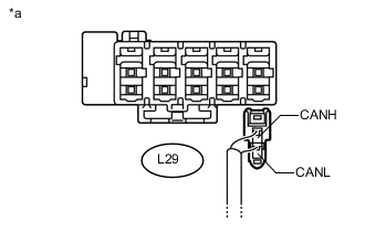
Text in Illustration *a Rear view of wire harness connector
(to No. 2 CAN Junction Connector)
Disconnect the L29 No. 2 CAN junction connector.
-
Measure the resistance according to the value(s) in the table below.
Standard Resistance Tester Connection Switch Condition Specified Condition L29-1 (CANH) - L29-2 (CANL) Ignition switch off 108 to 132 Ω
NG
CONNECT CONNECTOR Click here
OK
-
-
CHECK FOR OPEN IN CAN BUS MAIN WIRE (NO. 2 CAN JUNCTION CONNECTOR - COMBINATION METER ASSEMBLY)
-

Text in Illustration *a Rear view of wire harness connector
(to No. 2 CAN Junction Connector)
Disconnect the L30 No. 2 CAN junction connector.
-
Measure the resistance according to the value(s) in the table below.
Standard Resistance Tester Connection Switch Condition Specified Condition L30-1 (CANH) - L30-2 (CANL) Ignition switch off 108 to 132 Ω
OK 
REPLACE NO. 2 CAN JUNCTION CONNECTOR
NG
CONNECT CONNECTOR Click here
-
-
CONNECT CONNECTOR
-
Reconnect the L29 No. 2 CAN junction connector.
NEXT
-
-
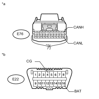
CHECK FOR OPEN IN CAN BUS MAIN WIRE (NO. 8 JUNCTION CONNECTOR - MAIN BODY ECU)
-
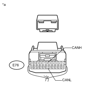
Text in Illustration *a Rear view of wire harness connector
(to No. 8 Junction Connector)
Disconnect the E76 No. 8 junction connector.
-
Measure the resistance according to the value(s) in the table below.
Standard Resistance Tester Connection Switch Condition Specified Condition E76-6 (CANH) - E76-17 (CANL) Ignition switch off 108 to 132 Ω
NG
CONNECT CONNECTOR Click here
OK
-
-
CHECK FOR OPEN IN CAN BUS MAIN WIRE (NO. 8 JUNCTION CONNECTOR - NO. 2 CAN JUNCTION CONNECTOR)
-
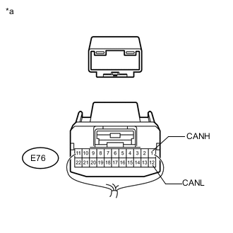
Text in Illustration *a Rear view of wire harness connector
(to No. 8 Junction Connector)
Measure the resistance according to the value(s) in the table below.
Standard Resistance Tester Connection Switch Condition Specified Condition E76-1 (CANH) - E76-12 (CANL) Ignition switch off 108 to 132 Ω
OK
REPLACE NO. 8 JUNCTION CONNECTOR
NG
REPAIR OR REPLACE CAN MAIN WIRE OR CONNECTOR (NO. 8 JUNCTION CONNECTOR - NO. 2 CAN JUNCTION CONNECTOR)
-
-
CONNECT CONNECTOR
-
Reconnect the E76 No. 8 junction connector.
NEXT
-
-
CHECK FOR OPEN IN CAN BUS MAIN WIRE (MAIN BODY ECU - NO. 8 JUNCTION CONNECTOR)
-
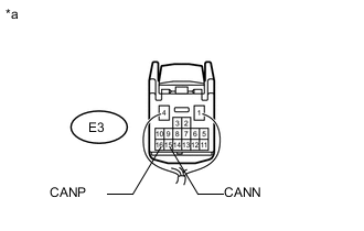
Text in Illustration *a Rear view of wire harness connector
(to Main Body ECU [Cowl Side Junction Block LH])
Disconnect the E3 main body ECU (cowl side junction block LH) connector.
-
Measure the resistance according to the value(s) in the table below.
Standard Resistance Tester Connection Switch Condition Specified Condition E3-16 (CANP) - E3-15 (CANN) Ignition switch off 108 to 132 Ω
OK
REPLACE MAIN BODY ECU (COWL SIDE JUNCTION BLOCK LH)
NG
REPAIR OR REPLACE CAN MAIN WIRE CONNECTED TO MAIN BODY ECU (MAIN BODY ECU - NO. 8 JUNCTION CONNECTOR)
-
-
CONNECT CONNECTOR
-
Reconnect the L29 and L30 No. 2 CAN junction connectors.
NEXT
-
-
CHECK FOR OPEN IN CAN BUS MAIN WIRE (NO. 10 JUNCTION CONNECTOR - NO. 9 JUNCTION CONNECTOR)
-
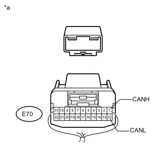
Text in Illustration *a Rear view of wire harness connector
(to No. 10 Junction Connector)
Disconnect the E70 No. 10 junction connector.
-
Measure the resistance according to the value(s) in the table below.
Standard Resistance Tester Connection Switch Condition Specified Condition E70-1 (CANH) - E70-12 (CANL) Ignition switch off 108 to 132 Ω
NG
CONNECT CONNECTOR Click here
OK
-
-
CHECK FOR OPEN IN CAN BUS MAIN WIRE (NO. 10 JUNCTION CONNECTOR - COMBINATION METER ASSEMBLY)
-

Text in Illustration *a Rear view of wire harness connector
(to No. 10 Junction Connector)
Measure the resistance according to the value(s) in the table below.
Standard Resistance Tester Connection Switch Condition Specified Condition E70-3 (CANH) - E70-14 (CANL) Ignition switch off 108 to 132 Ω
OK
REPLACE NO. 10 CAN JUNCTION CONNECTOR
NG
-
-
CONNECT CONNECTOR
-
Reconnect the E70 No. 10 junction connector.
NEXT
-
-
CHECK FOR OPEN IN CAN BUS MAIN WIRE (COMBINATION METER ASSEMBLY - NO. 10 JUNCTION CONNECTOR)
-
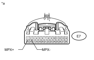
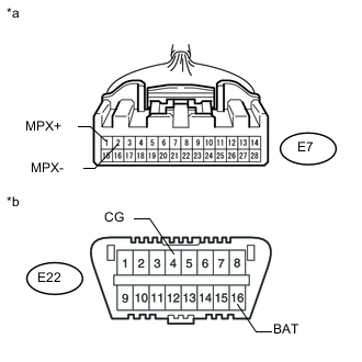
Text in Illustration *a Front view of wire harness connector
(to Combination Meter Assembly)
Disconnect the E7 combination meter assembly connector.
-
Measure the resistance according to the value(s) in the table below.
Standard Resistance Tester Connection Switch Condition Specified Condition E7-1 (MPX+) - E7-2 (MPX-) Ignition switch off 108 to 132 Ω Result Result Proceed to OK (w/ Multi-information Display) A OK (w/o Multi-information Display) B NG C
A
REPLACE COMBINATION METER ASSEMBLY Click here
B
REPLACE COMBINATION METER ASSEMBLY Click here
C
REPAIR OR REPLACE CAN MAIN WIRE CONNECTED TO COMBINATION METER ASSEMBLY (COMBINATION METER ASSEMBLY - NO. 10 JUNCTION CONNECTOR)
-
-
CONNECT CONNECTOR
-
Reconnect the E70 No. 10 junction connector.
NEXT
-
-
CHECK FOR OPEN IN CAN BUS MAIN WIRE (NO. 9 JUNCTION CONNECTOR - NO. 10 JUNCTION CONNECTOR)
-
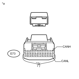
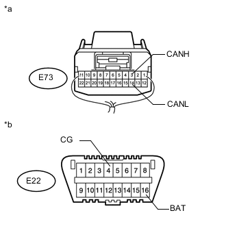
Text in Illustration *a Rear view of wire harness connector
(to No. 9 Junction Connector)
Disconnect the E73 No. 9 junction connector.
-
Measure the resistance according to the value(s) in the table below.
Standard Resistance Tester Connection Switch Condition Specified Condition E73-1 (CANH) - E73-12 (CANL) Ignition switch off 108 to 132 Ω
NG
REPAIR OR REPLACE CAN MAIN WIRE OR CONNECTOR (NO. 9 JUNCTION CONNECTOR - NO. 10 JUNCTION CONNECTOR)
OK
-
-
CHECK FOR OPEN IN CAN BUS MAIN WIRE (NO. 9 JUNCTION CONNECTOR - NO. 2 CAN JUNCTION CONNECTOR)
-
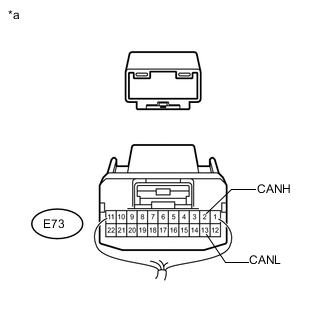
Text in Illustration *a Rear view of wire harness connector
(to No. 9 Junction Connector)
Measure the resistance according to the value(s) in the table below.
Standard Resistance Tester Connection Switch Condition Specified Condition E73-2 (CANH) - E73-13 (CANL) Ignition switch off 108 to 132 Ω
OK
REPLACE NO. 9 JUNCTION CONNECTOR
NG
REPAIR OR REPLACE CAN MAIN WIRE OR CONNECTOR (NO. 9 JUNCTION CONNECTOR - NO. 2 CAN JUNCTION CONNECTOR)
-
-
CHECK FOR SHORT IN CAN BUS WIRES (NO. 10 JUNCTION CONNECTOR SIDE)
-
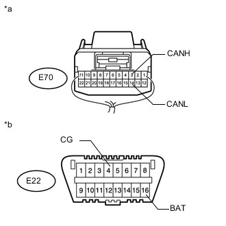
Text in Illustration *a Component with harness connected
(Main Body ECU [Cowl Side Junction Block LH])
*b Front view of DLC3 Disconnect the E70 No. 10 junction connector.
-
Measure the resistance according to the value(s) in the table below.
Standard Resistance Tester Connection Switch Condition Specified Condition E3-16 (CANP) - E3-15 (CANN) Ignition switch off 108 to 132 Ω E3-16 (CANP) - E22-4 (CG) Ignition switch off 200 Ω or higher E3-15 (CANN) - E22-4 (CG) Ignition switch off 200 Ω or higher E3-16 (CANP) - E22-16 (BAT) Ignition switch off 6 kΩ or higher E3-15 (CANN) - E22-16 (BAT) Ignition switch off 6 kΩ or higher
NG
CONNECT CONNECTOR Click here
OK
-
-
CHECK FOR SHORT IN CAN BUS WIRES (NO. 10 JUNCTION CONNECTOR - COMBINATION METER ASSEMBLY)
-
Text in Illustration *a Rear view of wire harness connector
(to No. 10 Junction Connector)
*b Front view of DLC3 Measure the resistance according to the value(s) in the table below.
Standard Resistance Tester Connection Switch Condition Specified Condition E70-3 (CANH) - E70-14 (CANN) Ignition switch off 108 to 132 Ω E70-3 (CANH) - E22-4 (CG) Ignition switch off 200 Ω or higher E70-14 (CANL) - E22-4 (CG) Ignition switch off 200 Ω or higher E70-3 (CANH) - E22-16 (BAT) Ignition switch off 6 kΩ or higher E70-14 (CANL) - E22-16 (BAT) Ignition switch off 6 kΩ or higher
OK
REPLACE NO. 10 JUNCTION CONNECTOR
NG
CONNECT CONNECTOR Click here
-
-
CONNECT CONNECTOR
-
Reconnect the E70 No. 10 junction connector.
NEXT
-
-
CHECK FOR SHORT IN CAN BUS WIRES (NO. 9 JUNCTION CONNECTOR - NO. 10 JUNCTION CONNECTOR)
-

Text in Illustration *a Rear view of wire harness connector
(to No. 9 Junction Connector)
*b Front view of DLC3 Disconnect the E73 No. 9 junction connector.
-
Measure the resistance according to the value(s) in the table below.
Standard Resistance Tester Connection Switch Condition Specified Condition E73-1 (CANH) - E73-12 (CANL) Ignition switch off 108 to 132 Ω E73-1 (CANH) - E22-4 (CG) Ignition switch off 200 Ω or higher E73-12 (CANL) - E22-4 (CG) Ignition switch off 200 Ω or higher E73-1 (CANH) - E22-16 (BAT) Ignition switch off 6 kΩ or higher E73-12 (CANL) - E22-16 (BAT) Ignition switch off 6 kΩ or higher
NG
REPAIR OR REPLACE CAN MAIN WIRE OR CONNECTOR (NO. 9 JUNCTION CONNECTOR - NO. 10 JUNCTION CONNECTOR)
OK
-
-
CHECK FOR SHORT IN CAN BUS WIRES (NO. 9 JUNCTION CONNECTOR SIDE)
-
Text in Illustration *a Component with harness connected
(Main Body ECU [Cowl Side Junction Block LH])
*b Front view of DLC3 Measure the resistance according to the value(s) in the table below.
Standard Resistance Tester Connection Switch Condition Specified Condition E3-16 (CANP) - E3-15 (CANN) Ignition switch off 108 to 132 Ω E3-16 (CANP) - E22-4 (CG) Ignition switch off 200 Ω or higher E3-15 (CANN) - E22-4 (CG) Ignition switch off 200 Ω or higher E3-16 (CANP) - E22-16 (BAT) Ignition switch off 6 kΩ or higher E3-15 (CANN) - E22-16 (BAT) Ignition switch off 6 kΩ or higher
NG
CONNECT CONNECTOR Click here
OK
-
-
CHECK FOR SHORT IN CAN BUS WIRES (NO. 9 JUNCTION CONNECTOR - WINDSHIELD WIPER ECU)
Note
For vehicles without an rain sensor, go to "Check for Short in CAN Bus Wires (No. 9 Junction Connector - Accessory Bus Buffer)".
-

Text in Illustration *a Rear view of wire harness connector
(to No. 9 Junction Connector)
*b Front view of DLC3 Measure the resistance according to the value(s) in the table below.
Standard Resistance Tester Connection Switch Condition Specified Condition E73-4 (CANH) - E73-15 (CANL) Ignition switch off 200 Ω or higher E73-4 (CANH) - E22-4 (CG) Ignition switch off 200 Ω or higher E73-15 (CANL) - E22-4 (CG) Ignition switch off 200 Ω or higher E73-4 (CANH) - E22-16 (BAT) Ignition switch off 6 kΩ or higher E73-15 (CANL) - E22-16 (BAT) Ignition switch off 6 kΩ or higher
NG
CONNECT CONNECTOR Click here
OK
-
-
CHECK FOR SHORT IN CAN BUS WIRES (NO. 9 JUNCTION CONNECTOR - ACCESSORY BUS BUFFER)
-
Text in Illustration *a Rear view of wire harness connector
(to No. 9 Junction Connector)
*b Front view of DLC3 Measure the resistance according to the value(s) in the table below.
Standard Resistance Tester Connection Switch Condition Specified Condition E73-3 (CANH) - E73-14 (CANL) Ignition switch off 200 Ω or higher E73-3 (CANH) - E22-4 (CG) Ignition switch off 200 Ω or higher E73-14 (CANL) - E22-4 (CG) Ignition switch off 200 Ω or higher E73-3 (CANH) - E22-16 (BAT) Ignition switch off 6 kΩ or higher E73-14 (CANL) - E22-16 (BAT) Ignition switch off 6 kΩ or higher
OK
REPLACE NO. 9 JUNCTION CONNECTOR
NG
CONNECT CONNECTOR Click here
-
-
CONNECT CONNECTOR
-
Reconnect the E73 No. 9 junction connector.
NEXT
-
-
CHECK FOR SHORT IN CAN BUS WIRES (NO. 2 CAN JUNCTION CONNECTOR - NO. 9 JUNCTION CONNECTOR)
-
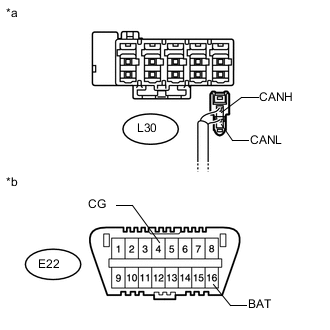
Text in Illustration *a Rear view of wire harness connector
(to No. 2 CAN Junction Connector)
*b Front view of DLC3 Disconnect the L30 No. 2 CAN junction connector.
-
Measure the resistance according to the value(s) in the table below.
Standard Resistance Tester Connection Switch Condition Specified Condition L30-1 (CANH) - L30-2 (CANL) Ignition switch off 108 to 132 Ω L30-1 (CANH) - E22-4 (CG) Ignition switch off 200 Ω or higher L30-2 (CANL) - E22-4 (CG) Ignition switch off 200 Ω or higher L30-1 (CANH) - E22-16 (BAT) Ignition switch off 6 kΩ or higher L30-2 (CANL) - E22-16 (BAT) Ignition switch off 6 kΩ or higher
NG
REPAIR OR REPLACE CAN MAIN WIRE OR CONNECTOR (NO. 2 CAN JUNCTION CONNECTOR - NO. 9 JUNCTION CONNECTOR)
OK
-
-
CHECK FOR SHORT IN CAN BUS WIRES (NO. 2 CAN JUNCTION CONNECTOR SIDE)
-
Text in Illustration *a Component with harness connected
(Main Body ECU [Cowl Side Junction Block LH])
*b Front view of DLC3 Disconnect the L29 No. 2 CAN junction connector.
-
Measure the resistance according to the value(s) in the table below.
Standard Resistance Tester Connection Switch Condition Specified Condition E3-16 (CANP) - E3-15 (CANN) Ignition switch off 108 to 132 Ω E3-16 (CANP) - E22-4 (CG) Ignition switch off 200 Ω or higher E3-15 (CANN) - E22-4 (CG) Ignition switch off 200 Ω or higher E3-16 (CANP) - E22-16 (BAT) Ignition switch off 6 kΩ or higher E3-15 (CANN) - E22-16 (BAT) Ignition switch off 6 kΩ or higher
NG
CONNECT CONNECTOR Click here
OK
-
-
CHECK FOR SHORT IN CAN BUS WIRES (NO. 2 CAN JUNCTION CONNECTOR - POWER BACK DOOR ECU)
Note
For vehicles without a power back door system, go to "Check for Short in CAN Bus Wires (No. 2 CAN Junction Connector - Tire Pressure Warning ECU)".
-

Text in Illustration *a Rear view of wire harness connector
(to No. 2 CAN Junction Connector)
*b Front view of DLC3 Disconnect the L54 No. 2 CAN junction connector.
-
Measure the resistance according to the value(s) in the table below.
Standard Resistance Tester Connection Switch Condition Specified Condition L54-1 (CANH) - L54-2 (CANL) Ignition switch off 200 Ω or higher L54-1 (CANH) - E22-4 (CG) Ignition switch off 200 Ω or higher L54-2 (CANL) - E22-4 (CG) Ignition switch off 200 Ω or higher L54-1 (CANH) - E22-16 (BAT) Ignition switch off 6 kΩ or higher L54-2 (CANH) - E22-16 (BAT) Ignition switch off 6 kΩ or higher
NG
CONNECT CONNECTOR Click here
OK
-
-
CHECK FOR SHORT IN CAN BUS WIRES (NO. 2 CAN JUNCTION CONNECTOR - NO. 2 MAIN BODY ECU)
-
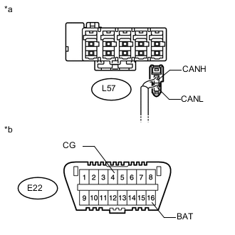
Text in Illustration *a Rear view of wire harness connector
(to No. 2 CAN Junction Connector)
*b Front view of DLC3 Disconnect the L57 No. 2 CAN junction connector.
-
Measure the resistance according to the value(s) in the table below.
Standard Resistance Tester Connection Switch Condition Specified Condition L57-1 (CANH) - L57-2 (CANL) Ignition switch off 200 Ω or higher L57-1 (CANH) - E22-4 (CG) Ignition switch off 200 Ω or higher L57-2 (CANL) - E22-4 (CG) Ignition switch off 200 Ω or higher L57-1 (CANH) - E22-16 (BAT) Ignition switch off 6 kΩ or higher L57-2 (CANH) - E22-16 (BAT) Ignition switch off 6 kΩ or higher
NG
CONNECT CONNECTOR Click here
OK
-
-
CHECK FOR SHORT IN CAN BUS WIRES (NO. 2 CAN JUNCTION CONNECTOR - TIRE PRESSURE WARNING ECU)
Note
For vehicles without a tire pressure warning system, go to "Replace No. 2 CAN Junction Connector".
-
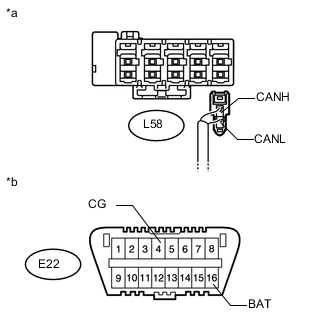
Text in Illustration *a Rear view of wire harness connector
(to No. 2 CAN Junction Connector)
*b Front view of DLC3 Disconnect the L58 No. 2 CAN junction connector.
-
Measure the resistance according to the value(s) in the table below.
Standard Resistance Tester Connection Switch Condition Specified Condition L58-1 (CANH) - L58-2 (CANL) Ignition switch off 200 Ω or higher L58-1 (CANH) - E22-4 (CG) Ignition switch off 200 Ω or higher L58-2 (CANL) - E22-4 (CG) Ignition switch off 200 Ω or higher L58-1 (CANH) - E22-16 (BAT) Ignition switch off 6 kΩ or higher L58-2 (CANH) - E22-16 (BAT) Ignition switch off 6 kΩ or higher
OK
REPLACE NO. 2 CAN JUNCTION CONNECTOR
NG
CONNECT CONNECTOR Click here
-
-
CONNECT CONNECTOR
-
Reconnect the L29 and L30 No. 2 CAN junction connectors.
NEXT
-
-
CHECK FOR SHORT IN CAN BUS WIRES (NO. 8 JUNCTION CONNECTOR - NO. 2 CAN JUNCTION CONNECTOR)
-
Text in Illustration *a Rear view of wire harness connector
(to No. 8 Junction Connector)
*b Front view of DLC3 Disconnect the E76 No. 8 junction connector.
-
Measure the resistance according to the value(s) in the table below.
Standard Resistance Tester Connection Switch Condition Specified Condition E76-1 (CANH) - E76-12 (CANL) Ignition switch off 108 to 132 Ω E76-1 (CANH) - E22-4 (CG) Ignition switch off 200 Ω or higher E76-12 (CANL) - E22-4 (CG) Ignition switch off 200 Ω or higher E76-1 (CANH) - E22-16 (BAT) Ignition switch off 6 kΩ or higher E76-12 (CANL) - E22-16 (BAT) Ignition switch off 6 kΩ or higher
NG
REPAIR OR REPLACE CAN MAIN WIRE OR CONNECTOR (NO. 8 JUNCTION CONNECTOR - NO. 2 CAN JUNCTION CONNECTOR)
OK
-
-
CHECK FOR SHORT IN CAN BUS WIRES (NO. 8 JUNCTION CONNECTOR - CERTIFICATION ECU)
Note
For vehicles without an entry and start system, go to "Check for Short in CAN Bus Wires (No. 8 Junction Connector - Position Control and Switch)".
-
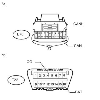
Text in Illustration *a Rear view of wire harness connector
(to No. 8 Junction Connector)
*b Front view of DLC3 Measure the resistance according to the value(s) in the table below.
Standard Resistance Tester Connection Switch Condition Specified Condition E76-2 (CANH) - E76-13 (CANL) Ignition switch off 200 Ω or higher E76-2 (CANH) - E22-4 (CG) Ignition switch off 200 Ω or higher E76-13 (CANL) - E22-4 (CG) Ignition switch off 200 Ω or higher E76-2 (CANH) - E22-16 (BAT) Ignition switch off 6 kΩ or higher E76-13 (CANL) - E22-16 (BAT) Ignition switch off 6 kΩ or higher
NG
CONNECT CONNECTOR Click here
OK
-
-
CHECK FOR SHORT IN CAN BUS WIRES (NO. 8 JUNCTION CONNECTOR - POSITION CONTROL ECU AND SWITCH)
Note
For vehicles without seat memory, go to "Check for Short in CAN Bus Wires (No. 8 Junction Connector - Multiplex Tilt and Telescopic ECU)".
-
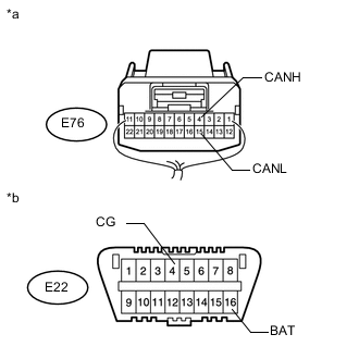
Text in Illustration *a Rear view of wire harness connector
(to No. 8 Junction Connector)
*b Front view of DLC3 Measure the resistance according to the value(s) in the table below.
Standard Resistance Tester Connection Switch Condition Specified Condition E76-4 (CANH) - E76-15 (CANL) Ignition switch off 200 Ω or higher E76-4 (CANH) - E22-4 (CG) Ignition switch off 200 Ω or higher E76-15 (CANL) - E22-4 (CG) Ignition switch off 200 Ω or higher E76-4 (CANH) - E22-16 (BAT) Ignition switch off 6 kΩ or higher E76-15 (CANL) - E22-16 (BAT) Ignition switch off 6 kΩ or higher
NG
CONNECT CONNECTOR Click here
OK
-
-
CHECK FOR SHORT IN CAN BUS WIRES (NO. 8 JUNCTION CONNECTOR - OUTER MIRROR CONTROL ECU ASSEMBLY)
-

Text in Illustration *a Rear view of wire harness connector
(to No. 8 Junction Connector)
*b Front view of DLC3 Measure the resistance according to the value(s) in the table below.
Standard Resistance Tester Connection Switch Condition Specified Condition E76-5 (CANH) - E76-16 (CANL) Ignition switch off 200 Ω or higher E76-5 (CANH) - E22-4 (CG) Ignition switch off 200 Ω or higher E76-16 (CANL) - E22-4 (CG) Ignition switch off 200 Ω or higher E76-5 (CANH) - E22-16 (BAT) Ignition switch off 6 kΩ or higher E76-16 (CANL) - E22-16 (BAT) Ignition switch off 6 kΩ or higher
NG
CONNECT CONNECTOR Click here
OK
-
-
CHECK FOR SHORT IN CAN BUS WIRES (NO. 8 JUNCTION CONNECTOR - MULTIPLEX TILT AND TELESCOPIC ECU)
Note
For vehicles without a power tilt and power telescopic steering column system, go to "Check for Short in CAN Bus Wires (No. 8 Junction Connector - Main Body ECU)".
-

Text in Illustration *a Rear view of wire harness connector
(to No. 8 Junction Connector)
*b Front view of DLC3 Measure the resistance according to the value(s) in the table below.
Standard Resistance Tester Connection Switch Condition Specified Condition E76-3 (CANH) - E76-14 (CANL) Ignition switch off 200 Ω or higher E76-3 (CANH) - E22-4 (CG) Ignition switch off 200 Ω or higher E76-14 (CANL) - E22-4 (CG) Ignition switch off 200 Ω or higher E76-3 (CANH) - E22-16 (BAT) Ignition switch off 6 kΩ or higher E76-14 (CANL) - E22-16 (BAT) Ignition switch off 6 kΩ or higher
NG
CONNECT CONNECTOR Click here
OK
-
-
CHECK FOR SHORT IN CAN BUS WIRES (NO. 8 JUNCTION CONNECTOR - MAIN BODY ECU)
-
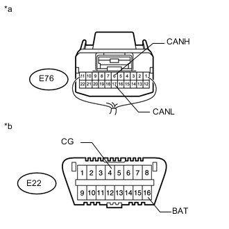
Text in Illustration *a Rear view of wire harness connector
(to No. 8 Junction Connector)
*b Front view of DLC3 Measure the resistance according to the value(s) in the table below.
Standard Resistance Tester Connection Switch Condition Specified Condition E76-6 (CANH) - E76-17 (CANL) Ignition switch off 108 to 132 Ω E76-6 (CANH) - E22-4 (CG) Ignition switch off 200 Ω or higher E76-17 (CANL) - E22-4 (CG) Ignition switch off 200 Ω or higher E76-6 (CANH) - E22-16 (BAT) Ignition switch off 6 kΩ or higher E76-17 (CANL) - E22-16 (BAT) Ignition switch off 6 kΩ or higher
OK
REPLACE NO. 8 JUNCTION CONNECTOR
NG
CONNECT CONNECTOR Click here
-
-
CONNECT CONNECTOR
-
Reconnect the E70 No. 10 junction connector.
NEXT
-
-
CHECK FOR SHORT IN CAN BUS WIRES (COMBINATION METER ASSEMBLY)
-
Text in Illustration *a Front view of wire harness connector
(to Combination Meter Assembly)
*b Front view of DLC3 Disconnect the E7 combination meter assembly connector.
-
Measure the resistance according to the value(s) in the table below.
Standard Resistance Tester Connection Switch Condition Specified Condition E7-1 (MPX+) - E7-2 (MPX-) Ignition switch off 108 to 132 Ω E7-1 (MPX+) - E22-4 (CG) Ignition switch off 200 Ω or higher E7-2 (MPX-) - E22-4 (CG) Ignition switch off 200 Ω or higher E7-1 (MPX+) - E22-16 (BAT) Ignition switch off 6 kΩ or higher E7-2 (MPX-) - E22-16 (BAT) Ignition switch off 6 kΩ or higher Result Result Proceed to OK (w/ Multi-information Display) A OK (w/o Multi-information Display) B NG C
A
REPLACE COMBINATION METER ASSEMBLY Click here
B
REPLACE COMBINATION METER ASSEMBLY Click here
C
REPAIR OR REPLACE CAN MAIN WIRE CONNECTED TO COMBINATION METER ASSEMBLY (MPX+, MPX-)
-
-
CONNECT CONNECTOR
-
Reconnect the E73 No. 9 junction connector.
NEXT
-
-
CHECK FOR SHORT IN CAN BUS WIRES (WINDSHIELD WIPER ECU)
-
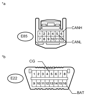
Text in Illustration *a Front view of wire harness connector
(to Windshield Wiper ECU)
*b Front view of DLC3 Disconnect the E85 windshield wiper ECU connector.
-
Measure the resistance according to the value(s) in the table below.
Standard Resistance Tester Connection Switch Condition Specified Condition E85-6 (CANH) - E85-5 (CANL) Ignition switch off 54 to 69 Ω E85-6 (CANH) - E22-4 (CG) Ignition switch off 200 Ω or higher E85-5 (CANL) - E22-4 (CG) Ignition switch off 200 Ω or higher E85-6 (CANH) - E22-16 (BAT) Ignition switch off 6 kΩ or higher E85-5 (CANL) - E22-16 (BAT) Ignition switch off 6 kΩ or higher
OK
REPLACE WINDSHIELD WIPER ECU Click here
NG
REPAIR OR REPLACE CAN BRANCH WIRE CONNECTED TO WINDSHIELD WIPER ECU (CANH, CANL)
-
-
CONNECT CONNECTOR
-
Reconnect the E73 No. 9 junction connector.
NEXT
-
-
CHECK FOR SHORT IN CAN BUS WIRES (ACCESSORY BUS BUFFER)
-
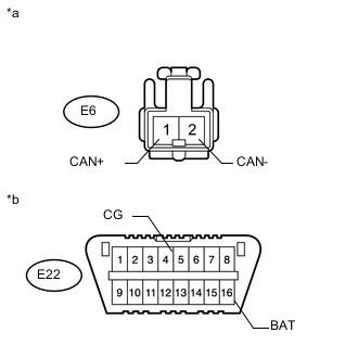
Text in Illustration *a Front view of wire harness connector
(to Accessory Bus Buffer)
*b Front view of DLC3 Disconnect the E6 accessory bus buffer connector.
-
Measure the resistance according to the value(s) in the table below.
Standard Resistance Tester Connection Switch Condition Specified Condition E6-1 (CAN+) - E6-2 (CAN-) Ignition switch off 54 to 69 Ω E6-1 (CAN+) - E22-4 (CG) Ignition switch off 200 Ω or higher E6-2 (CAN-) - E22-4 (CG) Ignition switch off 200 Ω or higher E6-1 (CAN+) - E22-16 (BAT) Ignition switch off 6 kΩ or higher E6-2 (CAN-) - E22-16 (BAT) Ignition switch off 6 kΩ or higher
OK
REPLACE ACCESSORY BUS BUFFER
NG
REPAIR OR REPLACE CAN BRANCH WIRE CONNECTED TO ACCESSORY BUS BUFFER (CAN+, CAN-)
-
-
CONNECT CONNECTOR
-
Reconnect the L29, L30 and L54 No. 2 CAN junction connectors.
NEXT
-
-
CHECK FOR SHORT IN CAN BUS WIRES (POWER BACK DOOR ECU)
-
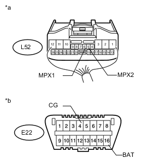
Text in Illustration *a Rear view of wire harness connector
(to Power Back Door Unit Assembly [Power Back Door ECU])
*b Front view of DLC3 Disconnect the L52 power back door unit assembly (power back door ECU) connector.
-
Measure the resistance according to the value(s) in the table below.
Standard Resistance Tester Connection Switch Condition Specified Condition L52-6 (MPX1) - L52-5 (MPX2) Ignition switch off 54 to 69 Ω L52-6 (MPX1) - E22-4 (CG) Ignition switch off 200 Ω or higher L52-5 (MPX2) - E22-4 (CG) Ignition switch off 200 Ω or higher L52-6 (MPX1) - E22-16 (BAT) Ignition switch off 6 kΩ or higher L52-5 (MPX2) - E22-16 (BAT) Ignition switch off 6 kΩ or higher
OK
REPLACE POWER BACK DOOR UNIT ASSEMBLY (POWER BACK DOOR ECU) Click here
NG
REPAIR OR REPLACE CAN BRANCH WIRE CONNECTED TO POWER BACK DOOR ECU (MPX1, MPX2)
-
-
CONNECT CONNECTOR
-
Reconnect the L29, L30, L54 and L57 No. 2 CAN junction connectors.
NEXT
-
-
CHECK FOR SHORT IN CAN BUS WIRES (NO. 2 MAIN BODY ECU)
-
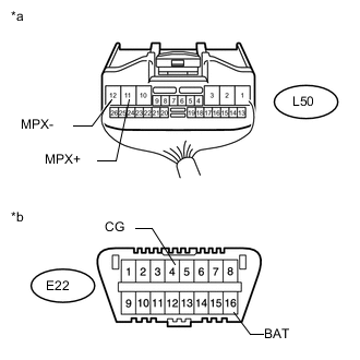
Text in Illustration *a Rear view of wire harness connector
(to No. 2 Main Body ECU)
*b Front view of DLC3 Disconnect the L50 No. 2 main body ECU connector.
-
Measure the resistance according to the value(s) in the table below.
Standard Resistance Tester Connection Switch Condition Specified Condition L50-11 (MPX+) - L50-12 (MPX-) Ignition switch off 54 to 69 Ω L50-11 (MPX+) - E22-4 (CG) Ignition switch off 200 Ω or higher L50-12 (MPX-) - E22-4 (CG) Ignition switch off 200 Ω or higher L50-11 (MPX+) - E22-16 (BAT) Ignition switch off 6 kΩ or higher L50-12 (MPX-) - E22-16 (BAT) Ignition switch off 6 kΩ or higher
OK
REPLACE NO. 2 MAIN BODY ECU Click here
NG
REPAIR OR REPLACE CAN BRANCH WIRE CONNECTED TO NO. 2 MAIN BODY ECU (MPX+, MPX-)
-
-
CONNECT CONNECTOR
-
Reconnect the L29, L30, L54, L57 and L58 No. 2 CAN junction connectors.
NEXT
-
-
CHECK FOR SHORT IN CAN BUS WIRES (TIRE PRESSURE WARNING ECU)
-
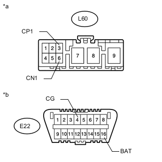
Text in Illustration *a Front view of wire harness connector
(to Tire Pressure Warning ECU and Receiver)
*b Front view of DLC3 Disconnect the L60 tire pressure warning ECU and receiver connector.
-
Measure the resistance according to the value(s) in the table below.
Standard Resistance Tester Connection Switch Condition Specified Condition L60-3 (CP1) - L60-6 (CN1) Ignition switch off 54 to 69 Ω L60-3 (CP1) - E22-4 (CG) Ignition switch off 200 Ω or higher L60-6 (CN1) - E22-4 (CG) Ignition switch off 200 Ω or higher L60-3 (CP1) - E22-16 (BAT) Ignition switch off 6 kΩ or higher L60-6 (CN1) - E22-16 (BAT) Ignition switch off 6 kΩ or higher
OK
REPLACE TIRE PRESSURE WARNING ECU AND RECEIVER Click here
NG
REPAIR OR REPLACE CAN BRANCH WIRECONNECTED TO TIRE PRESSUREWARNING ECU (CP1, CN1)
-
-
CONNECT CONNECTOR
-
Reconnect the E76 No. 8 junction connector.
NEXT
-
-
CHECK FOR SHORT IN CAN BUS WIRES (CERTIFICATION ECU)
-
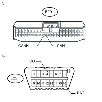
Text in Illustration *a Front view of wire harness connector
(to Certification ECU [Smart Key ECU Assembly])
*b Front view of DLC3 Disconnect the E29 certification ECU (smart key ECU assembly) connector.
-
Measure the resistance according to the value(s) in the table below.
Standard Resistance Tester Connection Switch Condition Specified Condition E29-27 (CANH) - E29-28 (CANL) Ignition switch off 54 to 69 Ω E29-27 (CANH) - E22-4 (CG) Ignition switch off 200 Ω or higher E29-28 (CANL) - E22-4 (CG) Ignition switch off 200 Ω or higher E29-27 (CANH) - E22-16 (BAT) Ignition switch off 6 kΩ or higher E29-28 (CANL) - E22-16 (BAT) Ignition switch off 6 kΩ or higher
OK
REPLACE CERTIFICATION ECU (SMART KEY ECU ASSEMBLY)
NG
REPAIR OR REPLACE CAN BRANCH WIRE CONNECTED TO CERTIFICATION ECU (CANH, CANL)
-
-
CONNECT CONNECTOR
-
Reconnect the E76 No. 8 junction connector.
NEXT
-
-
CHECK FOR SHORT IN CAN BUS WIRES (POSITION CONTROL ECU AND SWITCH)
-
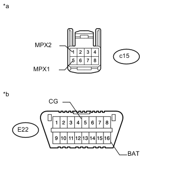
Text in Illustration *a Front view of wire harness connector
(to Position Control ECU and Switch)
*b Front view of DLC3 Disconnect the c15 position control ECU and switch connector.
-
Measure the resistance according to the value(s) in the table below.
Standard Resistance Tester Connection Switch Condition Specified Condition c15-5 (MPX1) - c15-1 (MPX2) Ignition switch off 54 to 69 Ω c15-5 (MPX1) - E22-4 (CG) Ignition switch off 200 Ω or higher c15-1 (MPX2) - E22-4 (CG) Ignition switch off 200 Ω or higher c15-5 (MPX1) - E22-16 (BAT) Ignition switch off 6 kΩ or higher c15-1 (MPX2) - E22-16 (BAT) Ignition switch off 6 kΩ or higher
OK
REPLACE POSITION CONTROL ECU AND SWITCH Click here
NG
REPAIR OR REPLACE CAN BRANCH WIRE CONNECTED TO POSITION CONTROL ECU AND SWITCH (MPX1, MPX2)
-
-
CONNECT CONNECTOR
-
Reconnect the E76 No. 8 junction connector.
NEXT
-
-
CHECK FOR SHORT IN CAN BUS WIRES (OUTER MIRROR CONTROL ECU ASSEMBLY)
-
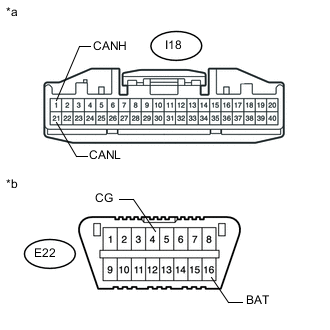
Text in Illustration *a Front view of wire harness connector
(to Outer Mirror Control ECU Assembly)
*b Front view of DLC3 Disconnect the I18 outer mirror control ECU assembly connector.
-
Measure the resistance according to the value(s) in the table below.
Standard Resistance Tester Connection Switch Condition Specified Condition I18-1 (CANH) - I18-21 (CANL) Ignition switch off 54 to 69 Ω I18-1 (CANH) - E22-4 (CG) Ignition switch off 200 Ω or higher I18-21 (CANL) - E22-4 (CG) Ignition switch off 200 Ω or higher I18-1 (CANH) - E22-16 (BAT) Ignition switch off 6 kΩ or higher I18-21 (CANL) - E22-16 (BAT) Ignition switch off 6 kΩ or higher
OK
REPLACE OUTER MIRROR CONTROL ECU ASSEMBLY Click here
NG
REPAIR OR REPLACE CAN BRANCH WIRE CONNECTED TO OUTER MIRROR CONTROL ECU ASSEMBLY (CANH, CANL)
-
-
CONNECT CONNECTOR
-
Reconnect the E76 No. 8 junction connector.
NEXT
-
-
CHECK FOR SHORT IN CAN BUS WIRES (MULTIPLEX TILT AND TELESCOPIC ECU)
-
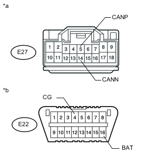
Text in Illustration *a Front view of wire harness connector
(to Multiplex Tilt and Telescopic ECU)
*b Front view of DLC3 Disconnect the E27 multiplex tilt and telescopic ECU connector.
-
Measure the resistance according to the value(s) in the table below.
Standard Resistance Tester Connection Switch Condition Specified Condition E27-5 (CANP) - E27-14 (CANN) Ignition switch off 54 to 69 Ω E27-5 (CANP) - E22-4 (CG) Ignition switch off 200 Ω or higher E27-14 (CANN) - E22-4 (CG) Ignition switch off 200 Ω or higher E27-5 (CANP) - E22-16 (BAT) Ignition switch off 6 kΩ or higher E27-14 (CANN) - E22-16 (BAT) Ignition switch off 6 kΩ or higher
OK
REPLACE MULTIPLEX TILT AND TELESCOPIC ECU Click here
NG
REPAIR OR REPLACE CAN BRANCH WIRE CONNECTED TO MULTIPLEX TILT AND TELESCOPIC ECU (CANP, CANN)
-
-
CONNECT CONNECTOR
-
Reconnect the E76 No. 8 junction connector.
NEXT
-
-
CHECK FOR SHORT IN CAN BUS WIRES (MAIN BODY ECU)
-
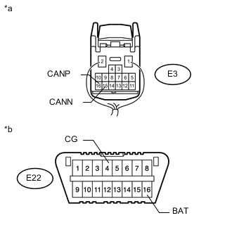
Text in Illustration *a Rear view of wire harness connector
(to Main Body ECU [Cowl Side Junction Block LH])
*b Front view of DLC3 Disconnect the E3 main body ECU (cowl side junction block LH) connector.
-
Measure the resistance according to the value(s) in the table below.
Standard Resistance Tester Connection Switch Condition Specified Condition E3-16 (CANP) - E3-15 (CANN) Ignition switch off 108 to 132 Ω E3-16 (CANP) - E22-4 (CG) Ignition switch off 200 Ω or higher E3-15 (CANN) - E22-4 (CG) Ignition switch off 200 Ω or higher E3-16 (CANP) - E22-16 (BAT) Ignition switch off 6 kΩ or higher E3-15 (CANN) - E22-16 (BAT) Ignition switch off 6 kΩ or higher
OK
REPLACE MAIN BODY ECU (COWL SIDE JUNCTION BLOCK LH)
NG
REPAIR OR REPLACE CAN MAIN WIRE CONNECTED TO MAIN BODY ECU (CANP, CANN)
-
-
CHECK HARNESS AND CONNECTOR (MAIN BODY ECU - BATTERY AND BODY GROUND)
-
Connect the cable to the negative (-) battery terminal.
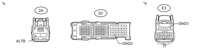
Text in Illustration *a Front view of wire harness connector
(to Main Body ECU [Cowl Side Junction Block LH])
*b Rear view of wire harness connector
(to Main Body ECU [Cowl Side Junction Block LH])
Note
When disconnecting the cable, some systems need to be initialized after the cable is reconnected Click here.
-
Disconnect the E3, 2A and 2D main body ECU (cowl side junction block LH) connectors.
-
Measure the voltage according to the value(s) in the table below.
Standard Voltage Tester Connection Condition Specified Condition 2A-1 (ALTB) - Body ground Always 11 to 14 V -
Measure the resistance according to the value(s) in the table below.
Standard Resistance Tester Connection Condition Specified Condition 2D-62 (GND2) - Body ground Always Below 1 Ω E3-1 (GND3) - Body ground Always Below 1 Ω
OK
REPLACE MAIN BODY ECU (COWL SIDE JUNCTION BLOCK LH)
NG
REPAIR OR REPLACE HARNESS OR CONNECTOR
-