CAN COMMUNICATION SYSTEM(for LHD) SYSTEM DIAGRAM
-
w/ Network Gateway ECU
Tech Tips
-
The master cylinder solenoid (skid control ECU) stores steering sensor and yaw rate sensor assembly DTCs and performs DTC communication by receiving information from the steering sensor and yaw rate sensor assembly.
-
The ECM uses the CAN communication system to perform DTC communication instead of the conventional communication line (SIL).
-
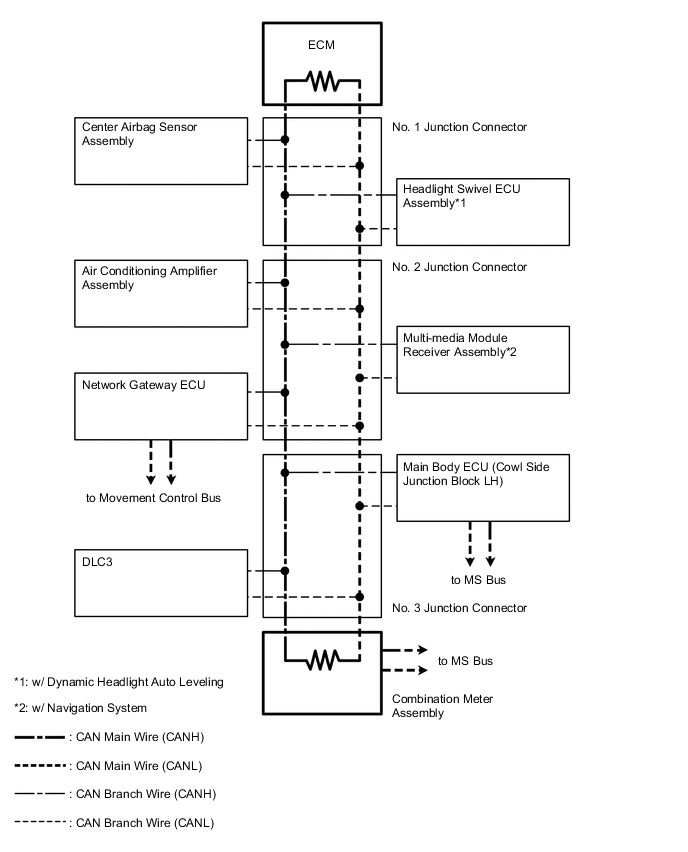
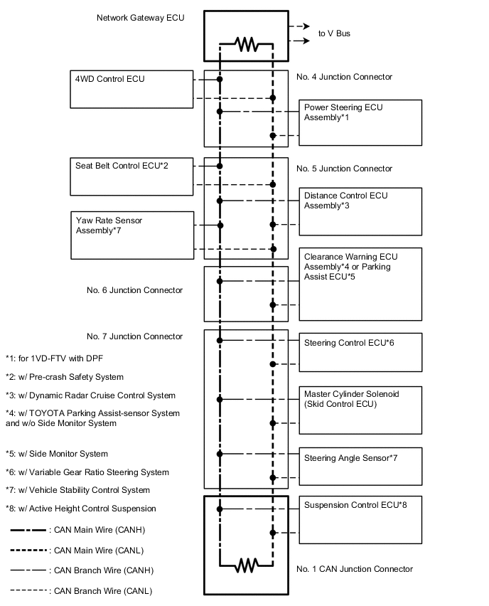
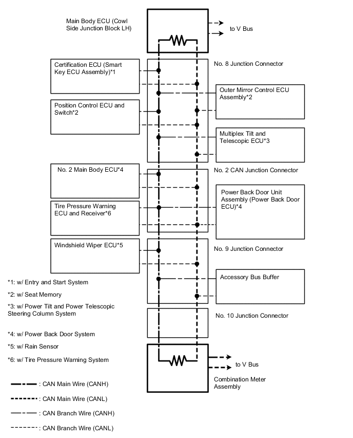
SYSTEM DIAGRAM
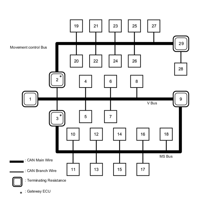
No. ECU/Sensor Name 1 ECM 2 Network gateway ECU 3 Main body ECU (cowl side junction block LH) 4 DLC3 5 Air conditioning amplifier assembly 6 Center airbag sensor assembly 7 Multi-media module receiver assembly*1 8 Headlight swivel ECU assembly*2 9 Combination meter assembly 10 Certification ECU (smart key ECU assembly)*3 11 Multiplex tilt and telescopic ECU*4 12 Outer mirror control ECU assembly*5 13 Windshield wiper ECU*6 14 Position control ECU and switch*5 15 Accessory bus buffer 16 Power back door unit assembly (power back door ECU)*7 17 Tire pressure warning ECU and receiver*16 18 No. 2 main body ECU*7 19 Master cylinder solenoid (skid control ECU) 20 Yaw rate sensor assembly*8 21 Steering control ECU*9 22 Steering angle sensor*8 23 4WD control ECU 24
-
Parking assist ECU*10
-
Clearance warning ECU assembly*11
25 Seat belt control ECU*12 26 Power steering ECU assembly*13 27 Distance control ECU assembly*14 28 Suspension control ECU*15 29 No. 1 CAN junction connector
-
*1: w/ Navigation System
-
*2: w/ Dynamic Headlight Auto Leveling
-
*3: w/ Entry and Start System
-
*4: w/ Power Tilt and Power Telescopic Steering Column System
-
*5: w/ Seat Memory
-
*6: w/ Rain Sensor
-
*7: w/ Power Back Door System
-
*8: w/ Vehicle Stability Control System
-
*9: w/ Variable Gear Ratio Steering System
-
*10: w/ Side Monitor System
-
*11: w/ TOYOTA Parking Assist-sensor System and w/o Side Monitor System
-
*12: w/ Pre-crash Safety System
-
*13: for 1VD-FTV with DPF
-
*14: w/ Dynamic Radar Cruise Control System
-
*15: w/ Active Height Control Suspension
-
*16: w/ Tire Pressure Warning System
-
-
V Bus
-
Movement Control Bus
-
MS Bus
-
-
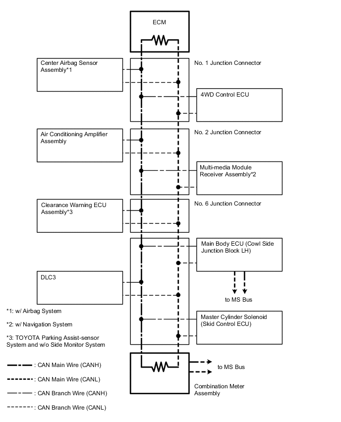
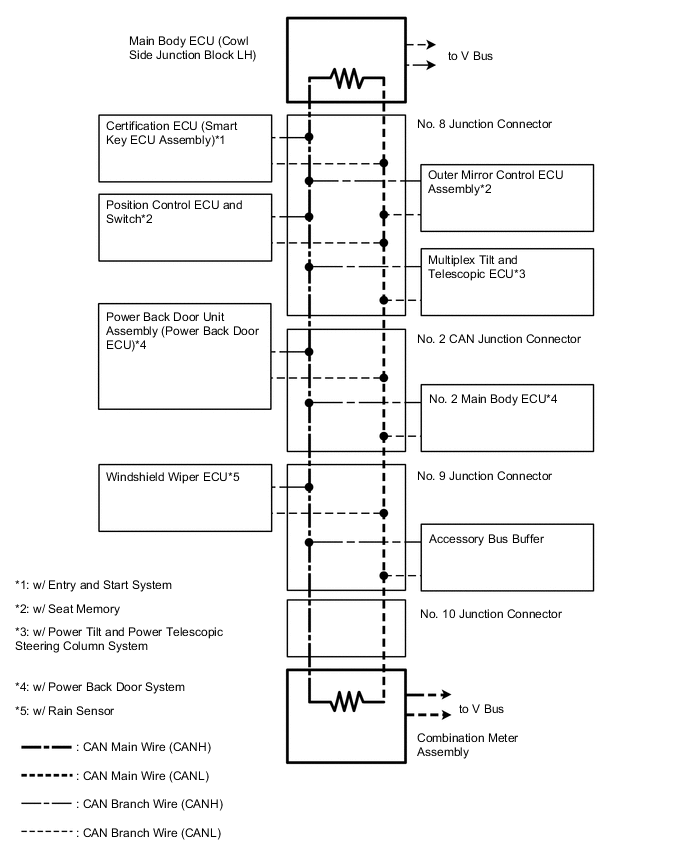
w/o Network Gateway ECU
Tech Tips
-
The master cylinder solenoid (skid control ECU) stores steering sensor and yaw rate sensor assembly DTCs and performs DTC communication by receiving information from the steering sensor and yaw rate sensor assembly.
-
The ECM uses the CAN communication system to perform DTC communication instead of the conventional communication line (SIL).
-
SYSTEM DIAGRAM
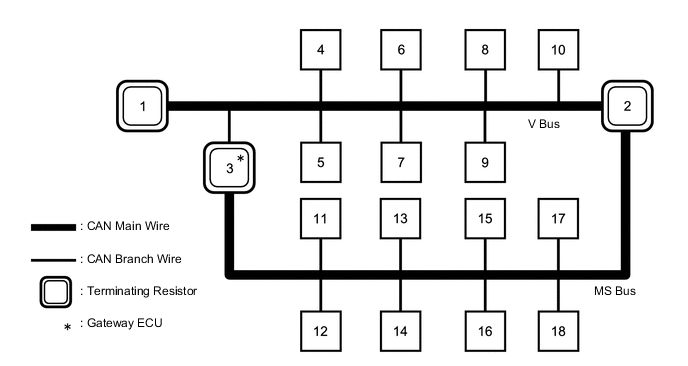
No. ECU/Sensor Name 1 ECM 2 Combination meter assembly 3 Main body ECU (cowl side junction block LH) 4 DLC3 5 Air conditioning amplifier assembly 6 Center airbag sensor assembly*1 7 Multi-media module receiver assembly*2 8 4WD control ECU 9 Clearance warning ECU assembly*3 10 Master cylinder solenoid (skid control ECU) 11 Certification ECU (smart key ECU assembly)*4 12 Multiplex tilt and telescopic ECU*5 13 Accessory bus buffer 14 Outer mirror control ECU assembly*6 15 Windshield wiper ECU*7 16 Position control ECU and switch*6 17 Power back door unit assembly (power back door ECU)*8 18 No. 2 main body ECU*8
-
*1: w/ Airbag System
-
*2: w/ Navigation System
-
*3: w/ TOYOTA Parking Assist-sensor System and w/o Side Monitor System
-
*4: w/ Entry and Start System
-
*5: w/ Power Tilt and Power Telescopic Steering Column System
-
*6: w/ Seat Memory
-
*7: w/ Rain Sensor
-
*8: w/ Power Back Door System
-
-
V Bus
-
MS Bus
Tech Tips
The ECM uses the CAN communication system to perform DTC communication instead of the conventional communication line (SIL).
-