LIN COMMUNICATION SYSTEM Rear Heater Control Panel LIN Communication Malfunction
DESCRIPTION
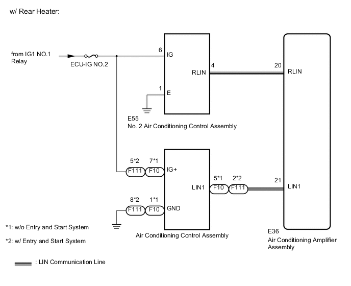
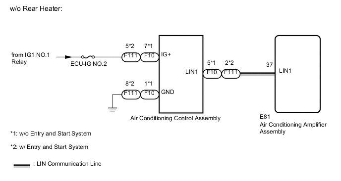
The LIN communication of the components related to the rear air conditioning occurs between the air conditioning amplifier, air conditioning control and No. 2 air conditioning control*.
-
*: w/ Rear heater
WIRING DIAGRAM
CAUTION / NOTICE / HINT
Note
-
When using the GTS with the ignition switch off to troubleshoot:
Connect the GTS to the vehicle, and turn a courtesy switch on and off at 1.5 second intervals until communication between the GTS and vehicle begins.
-
Inspect the fuses for circuits related to this system before performing the following inspection procedure.
PROCEDURE
-
CHECK AIR CONDITIONING TYPE
-
Check air conditioning type.
Result Result Proceed to w/ Rear Heater A w/o Rear Heater B
B 
CHECK HARNESS AND CONNECTOR (AIR CONDITIONING AMPLIFIER - AIR CONDITIONING CONTROL) Click here
A 
-
-
CHECK HARNESS AND CONNECTOR (AIR CONDITIONING AMPLIFIER - NO. 2 AIR CONDITIONING PANEL)
-
Disconnect the E36 amplifier connector
-
Disconnect the E55 panel connector.
-
Measure the resistance according to the value(s) in the tables below.
Standard Resistance Tester Connection Condition Specified Condition E36-20 (RLIN) - E55-4 (RLIN) Always Below 1 Ω E36-20 (RLIN) - Body ground Always Below 1 Ω
NG 
REPAIR OR REPLACE HARNESS OR CONNECTOR
OK
-
-
CHECK HARNESS AND CONNECTOR (NO. 2 AIR CONDITIONING CONTROL BATTERY AND BODY GROUND)
-
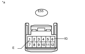
Text in Illustration *a Front view of wire harness connector
(to No. 2 Air Conditioning Control)
Disconnect the panel connector.
-
Measure the resistance and voltage according to the value(s) in the tables below.
Standard Resistance Tester Connection Condition Specified Condition E55-1 (E) - Body ground Always Below 1 Ω Standard Voltage Tester Connection Switch Condition Specified Condition E55-6 (IG) - Body ground Ignition switch ON 11 to 14 V
NG
REPAIR OR REPLACE HARNESS OR CONNECTOR
OK
-
-
CHECK NO. 2 AIR CONDITIONING CONTROL
-
Temporarily replace the No. 2 air conditioning control panel with a new or normally functioning one Click here.
-
Check that the rear air conditioning function is normal.
OK Rear air conditioning function is normal. Result Result Proceed to OK A NG (w/ Navigation System) B NG (w/o Navigation System) C
A
END (NO. 2 AIR CONDITIONING CONTROL IS DEFECTIVE)
C
REPLACE AIR CONDITIONING AMPLIFIER ASSEMBLY Click here
B
-
-
CHECK HARNESS AND CONNECTOR (AIR CONDITIONING AMPLIFIER - AIR CONDITIONING CONTROL)
-
*1: w/ Rear Heater
-
*2: w/o Rear Heater
-
*3: w/o Entry and Start System
-
*4: w/ Entry and Start System
-
Disconnect the E36*1 E81*2 amplifier connector
-
Disconnect the F10*3 or F111*4 panel connector.
-
Measure the resistance according to the value(s) in the tables below.
Standard Resistance w/ Rear Heater Tester Connection Condition Specified Condition E36-21 (LIN1) - F10-5 (LIN1)*3 Always Below 1 Ω E36-21 (LIN1) - F111-2 (LIN1)*4 Always Below 1 Ω E36-21 (LIN1) - Body ground Always 10 kΩ or higher w/o Rear Heater Tester Connection Condition Specified Condition E81-37 (LIN1) - F10-5 (LIN1)*3 Always Below 1 Ω E81-37 (LIN1) - F111-2 (LIN1)*4 Always Below 1 Ω E81-37 (LIN1) - Body ground Always 10 kΩ or higher
NG
REPAIR OR REPLACE HARNESS OR CONNECTOR
OK
-
-
CHECK HARNESS AND CONNECTOR (AIR CONDITIONING CONTROL BATTERY AND BODY GROUND)
-
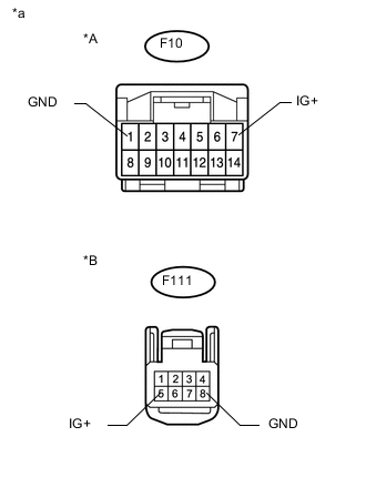
Text in Illustration *A w/o Entry and Start System *B w/ Entry and Start System *a Front view of wire harness connector
(to Air Conditioning Control)
Disconnect the panel connector.
-
Measure the resistance and voltage according to the value(s) in the tables below.
Standard Resistance w/o Entry and Start System Tester Connection Condition Specified Condition F10-1 (GND) - Body ground Always Below 1 Ω w/ Entry and Start System Tester Connection Condition Specified Condition F111-8 (GND) - Body ground Always Below 1 Ω Standard Voltage w/o Entry and Start System Tester Connection Switch Condition Specified Condition F10-7 (IG+) - Body ground Ignition switch ON 11 to 14 V w/ Entry and Start System Tester Connection Switch Condition Specified Condition F111-5 (IG+) - Body ground Ignition switch ON 11 to 14 V
NG
REPAIR OR REPLACE HARNESS OR CONNECTOR
OK
-
-
CHECK AIR CONDITIONING CONTROL ASSEMBLY
-
Temporarily replace the air conditioning control with a new or normally functioning one.
-
w/o Entry and Start System: Click here
-
w/o Navigation System: Click here
-
-
Check the that front air conditioning function is normal.
OK Front air conditioning function is normal.
OK
END (AIR CONDITIONING CONTROL ASSEMBLY IS DEFECTIVE)
NG
REPLACE AIR CONDITIONING AMPLIFIER ASSEMBLY Click here
-