PROCEDURE
-
Table 1. *a Hold *b TurnClick here
REMOVE GENERATOR PULLEY
09820-63011 09820-06010 09820-06021 Tip:SST 1-A and 1-B 09820-06010 SST 2 09820-06021
-
Hold SST 1-A with a torque wrench, and tighten SST 1-B clockwise to the specified torque.
39 N*m 398 kgf*cm 29 ft.*lbf Note:Check that SST is secured on the rotor shaft.
-

Table 2. *a Insert Mount SST 2 in a vise.
-
Insert SST 1-A and 1-B into SST 2, and attach the pulley nut to SST 2.
-
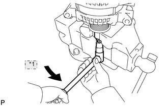
Table 3. *1 Turn To loosen the pulley nut, turn SST 1-A in the direction shown in the illustration.
Note:To prevent damage to the rotor shaft, do not loosen the pulley nut more than one-half turn.
-
Remove the generator from SST 2.
-
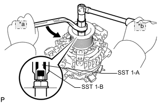
Table 4. *a Turn *b Hold Turn SST 1-B, and remove SST 1-A and 1-B.
-
Remove the pulley nut and pulley.
-
- Click here
REMOVE GENERATOR REAR END COVER
-
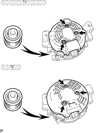
Table 5. *1 130 A Type and 150 A Type: *2 180 A Type: Place the generator on the pulley.
-
Remove the 3 nuts and end cover.
-
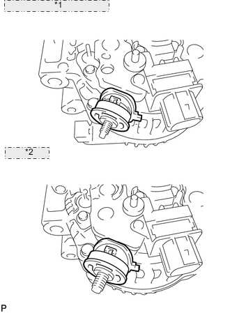
Table 6. *1 130 A Type and 150 A Type: *2 180 A Type: Remove the terminal insulator.
-
- Click here
REMOVE GENERATOR BRUSH HOLDER ASSEMBLY
-
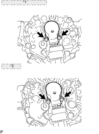
Table 7. *1 130 A Type and 150 A Type: *2 180 A Type: Remove the 2 screws and brush holder.
-
- Click here
REMOVE GENERATOR COIL ASSEMBLY
-
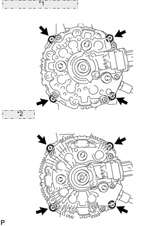
Table 8. *1 130 A Type and 150 A Type: *2 180 A Type: Remove the 4 bolts.
-
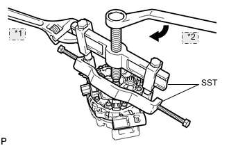
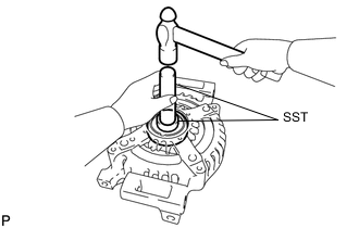
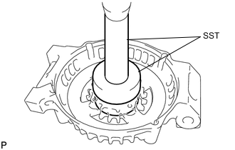
Table 9. *1 Hold *2 Turn Using SST, remove the coil assembly.
09950-40011 09951-04020 09952-04010 09953-04020 09954-04010 09955-04071 09957-04010 09958-04011
-
- Click here
REMOVE GENERATOR ROTOR ASSEMBLY
-
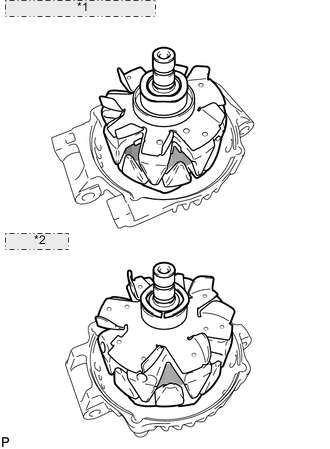
Table 10. *1 130 A Type and 150 A Type: *2 180 A Type: Remove the generator washer and rotor.
-
- Click here
REPLACE GENERATOR DRIVE END FRAME BEARING
-
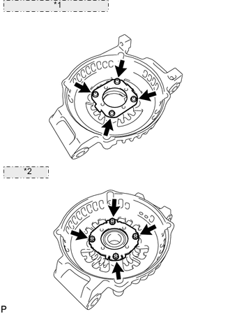
Table 11. *1 130 A Type and 150 A Type: *2 180 A Type: Remove the 4 screws and retainer plate.
-
Using SST and a hammer, tap out the bearing.
09950-60010 09951-00250 09950-70010 09951-07100 -
Using SST and a press, press in a new bearing.
09950-60010 09951-00470 09950-70010 09951-07100 -
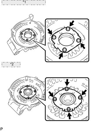
Table 12. *1 130 A Type and 150 A Type: *2 180 A Type: 130 A Type and 150 A Type:
Install the retainer plate with the 4 screws.
2.3 N*m 23 kgf*cm 20 in.*lbf -
180 A Type:
Install the retainer plate with the 4 screws.
3.0 N*m 30 kgf*cm 26 in.*lbf
-