LIN COMMUNICATION SYSTEM TERMINALS OF ECU
-
CHECK MAIN BODY ECU (MULTIPLEX NETWORK BODY ECU), COWL SIDE JUNCTION BLOCK LH
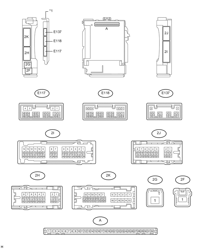
Text in Illustration *1 Main Body ECU (Multiplex Network Body ECU) - -
-
Remove the main body ECU (multiplex network body ECU) from the cowl side junction block LH.
-
for LHD: Click here
-
for RHD: Click here
-
-
Reconnect the cowl side junction block LH connectors.
-
Measure the resistance and voltage according to the value(s) in the table below.
Terminal No. (Symbol) Wiring Color Terminal Description Condition Specified Condition A-31 (BECU) - Body ground - Battery power supply Always Below 1 Ω A-11 (GND1) - Body ground - Ground Always Below 1 Ω A-32 (IG) - Body ground - Ignition power supply (IG signal) Ignition switch ON → Off 11 to 14 V → Below 1 V A-30 (ACC) - Body ground - ACC power supply Ignition switch ACC → Off 11 to 14 V → Below 1 V
-
-
CHECK MULTIPLEX NETWORK MASTER SWITCH ASSEMBLY (for Models with Jam Protection Function on 4 Windows)

-
Disconnect the I11*1 or I22*2 multiplex network master switch connector.
-
Measure the resistance and voltage according to the value(s) in the table below.
Tech Tips
-
*1: for LHD
-
*2: for RHD
for LHD Terminal No. (Symbol) Wiring Color Terminal Description Condition Specified Condition I11-11 (B) - I11-12 (GND) R - W-B Ignition power supply Ignition switch off Below 1 Ω I11-11 (B) - I11-12 (GND) R - W-B Ignition power supply Ignition switch ON 11 to 14 V I11-12 (GND) - Body ground W-B - Body ground Ground Always Below 1 Ω for RHD Terminal No. (Symbol) Wiring Color Terminal Description Condition Specified Condition I22-11 (B) - I22-12 (GND) R - W-B Ignition power supply Ignition switch off Below 1 Ω I22-11 (B) - I22-12 (GND) R - W-B Ignition power supply Ignition switch ON 11 to 14 V I22-12 (GND) - Body ground W-B - Body ground Ground Always Below 1 Ω -
-
-
CHECK FRONT POWER WINDOW REGULATOR MOTOR ASSEMBLY LH (for Models with Jam Protection Function on 4 Windows)

-
Disconnect the I12 motor connector.
-
Measure the resistance and voltage according to the value(s) in the table below.
Terminal No. (Symbol) Wiring Color Terminal Description Condition Specified Condition I12-2 (B) - I12-1 (GND) L - W-B Battery power supply Always 11 to 14 V I12-1 (GND) - Body ground W-B - Body ground Ground Always Below 1 Ω
-
-
CHECK FRONT POWER WINDOW REGULATOR MOTOR ASSEMBLY RH (for Models with Jam Protection Function on 4 Windows)

-
Disconnect the I4 motor connector.
-
Measure the resistance and voltage according to the value(s) in the table below.
Terminal No. (Symbol) Wiring Color Terminal Description Condition Specified Condition I4-2 (B) - I4-1 (GND) L - W-B Battery power supply Always 11 to 14 V I4-1 (GND) - Body ground W-B - Body ground Ground Always Below 1 Ω
-
-
CHECK REAR POWER WINDOW REGULATOR MOTOR ASSEMBLY LH (for Models with Jam Protection Function on 4 Windows)

-
Disconnect the J11 motor connector.
-
Measure the resistance and voltage according to the value(s) in the table below.
Terminal No. (Symbol) Wiring Color Terminal Description Condition Specified Condition J11-2 (B) - J11-1 (GND) L - W-B Battery power supply Always 11 to 14 V J11-1 (GND) - Body ground W-B - Body ground Ground Always Below 1 Ω
-
-
CHECK REAR POWER WINDOW REGULATOR MOTOR ASSEMBLY RH (for Models with Jam Protection Function on 4 Windows)

-
Disconnect the J4 motor connector.
-
Measure the resistance and voltage according to the value(s) in the table below.
Terminal No. (Symbol) Wiring Color Terminal Description Condition Specified Condition J4-2 (B) - J4-1 (GND) L - W-B Battery power supply Always 11 to 14 V J4-1 (GND) - Body ground W-B - Body ground Ground Always Below 1 Ω
-
-
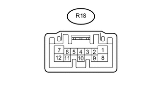
CHECK SLIDING ROOF DRIVE GEAR SUB-ASSEMBLY (SLIDING ROOF ECU) (w/ Sliding Roof System)
-
Disconnect the R18 ECU connector.
-
Measure the resistance and voltage according to the value(s) in the table below.
Terminal No. (Symbol) Wiring Color Terminal Description Condition Specified Condition R18-1 (B) - R18-12 (E) LA-L - W-B Battery power supply Always 11 to 14 V R18-12 (E) - Body ground W-B - Body ground Ground Always Below 1 Ω
-
-
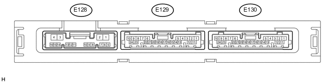
CHECK CERTIFICATION ECU (SMART KEY ECU ASSEMBLY) (w/ Entry and Start System)
-
Disconnect the E130 ECU connector.
-
Measure the resistance and voltage according to the value(s) in the table below.
Terminal No. (Symbol) Wiring Color Terminal Description Condition Specified Condition E130-10 (+B) - E130-11 (E) P - BR Battery power supply Always 11 to 14 V E130-11 (E) - Body ground BR - Body ground Ground Always Below 1 Ω
-
-
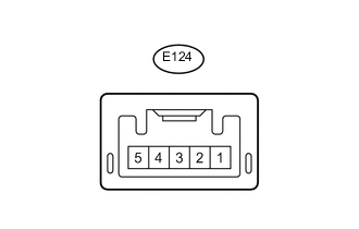
CHECK ID CODE BOX (IMMOBILISER CODE ECU) (w/ Entry and Start System)
-
Disconnect the E124 ECU connector.
-
Measure the resistance and voltage according to the value(s) in the table below.
Terminal No. (Symbol) Wiring Color Terminal Description Condition Specified Condition E124-1 (+B) - E124-5 (GND) W - BR Battery power supply Always 11 to 14 V E124-5 (GND) - Body ground BR - Body ground Ground Always Below 1 Ω
-
-
CHECK STEERING LOCK ACTUATOR ASSEMBLY (STEERING LOCK ECU)

-
Disconnect the E26 ECU connector.
-
Measure the resistance and voltage according to the value(s) in the table below.
Terminal No. (Symbol) Wiring Color Terminal Description Condition Specified Condition E26-7 (B) - E26-1 (GND) G - W-B Battery power supply Always 11 to 14 V E26-1 (GND) - Body ground W-B - Body ground Ground Always Below 1 Ω
-
-
CHECK AIR CONDITIONING AMPLIFIER (w/ Rear Heater)

-
Disconnect the E36 amplifier connector.
-
Measure the resistance and voltage according to the value(s) in the table below.
Terminal No. (Symbol) Wiring Color Terminal Description Condition Specified Condition E36-5 (IG+) - E36-1 (GND) G - BR IG power supply Ignition switch off Below 1 V E36-5 (IG+) - E36-1 (GND) G - BR IG power supply Ignition switch ON 11 to 14 V E36-6 (+B1) - E36-1 (GND) LG - BR Battery power supply Always 11 to 14 V E36-7 (+B2) - E36-1 (GND) LG - BR Battery power supply Always 11 to 14 V E36-1 (GND) - Body ground BR - Body ground Ground Always Below 1 Ω
-
-
CHECK AIR CONDITIONING AMPLIFIER (w/o Rear Heater)
-
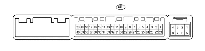
Disconnect the E81 amplifier connector.
-
Measure the resistance and voltage according to the value(s) in the table below.
Terminal No. (Symbol) Wiring Color Terminal Description Condition Specified Condition E81-21 (+B1) - E81-14 (GND) LG - BR Battery power supply Always 11 to 14 V E81-1 (IG+) - E81-14 (GND) G - BR IG power supply Ignition switch ON 11 to 14 V E81-1 (IG+) - E81-14 (GND) G - BR IG power supply Ignition switch off Below 1 V E81-14 (GND) - Body ground BR - Body ground Ground Always Below 1 Ω
-
-
CHECK AIR CONDITIONING CONTROL ASSEMBLY (w/o Entry and Start System)

-
Disconnect the F10 panel connector.
-
Measure the resistance and voltage according to the value(s) in the table below.
Terminal No. (Symbol) Wiring Color Terminal Description Condition Specified Condition F10-7 (IG+) - F10-1 (GND) B - W-B IG power supply Ignition switch ON 11 to 14 V F10-7 (IG+) - F10-1 (GND) B - W-B IG power supply Ignition switch off Below 1 V F10-1 (GND) - Body ground W-B - Body ground Ground Always Below 1 Ω
-
-
CHECK AIR CONDITIONING CONTROL ASSEMBLY (w/ Entry and Start System)
-
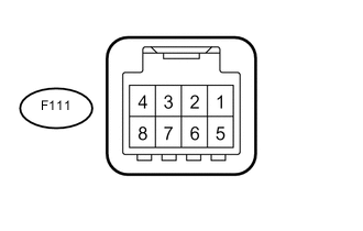
Disconnect the F111 panel connector.
-
Measure the resistance and voltage according to the value(s) in the table below.
Terminal No. (Symbol) Wiring Color Terminal Description Condition Specified Condition F111-5 (IG+) - F111-8 (GND) B - W-B IG power supply Ignition switch ON 11 to 14 V F111-5 (IG+) - F111-8 (GND) B - W-B IG power supply Ignition switch off Below 1 V F111-8 (GND) - Body ground W-B - Body ground Ground Always Below 1 Ω
-
-
CHECK NO. 2 AIR CONDITIONING CONTROL ASSEMBLY (w/ Rear Heater)

-
Disconnect the E55 panel connector.
-
Measure the resistance and voltage according to the value(s) in the table below.
Terminal No. (Symbol) Wiring Color Terminal Description Condition Specified Condition E55-6 (IG) - E55-1 (E) B - W-B IG power supply Ignition switch ON 11 to 14 V E55-6 (IG) - E55-1 (E) B - W-B IG power supply Ignition switch off Below 1 V E55-1 (E) - Body ground W-B - Body ground Ground Always Below 1 Ω
-
-
CHECK RAIN SENSOR (w/ Rain Sensor)

-
Disconnect the R11 rain sensor connector.
-
Measure the voltage according to the value(s) in the table below.
Terminal No. (Symbol) Wiring Color Terminal Description Condition Specified Condition R11-4 (SIG) - Body ground V - Body ground IG power supply Ignition switch off Below 1 V R11-4 (SIG) - Body ground V - Body ground IG power supply Ignition switch ON 11 to 14 V R11-2 (ES) - Body ground W - Body ground Ground circuit Always Below 1 V
-
-
CHECK WINDSHIELD WIPER ECU (w/ Rain Sensor)

-
Disconnect the E147 ECU connector.
-
Measure the voltage and resistance according to the value(s) in the table below.
Terminal No. (Symbol) Wiring Color Terminal Description Condition Specified Condition E147-2 (IG) - E147-12 (E) B - W-B IG power supply Ignition switch off Below 1 V E147-2 (IG) - E147-12 (E) B - W-B IG power supply Ignition switch ON 11 to 14 V E147-12 (E) - Body ground W-B - Body ground Ground circuit Always Below 1 Ω
-