LIN COMMUNICATION SYSTEM TERMINALS OF ECU
-
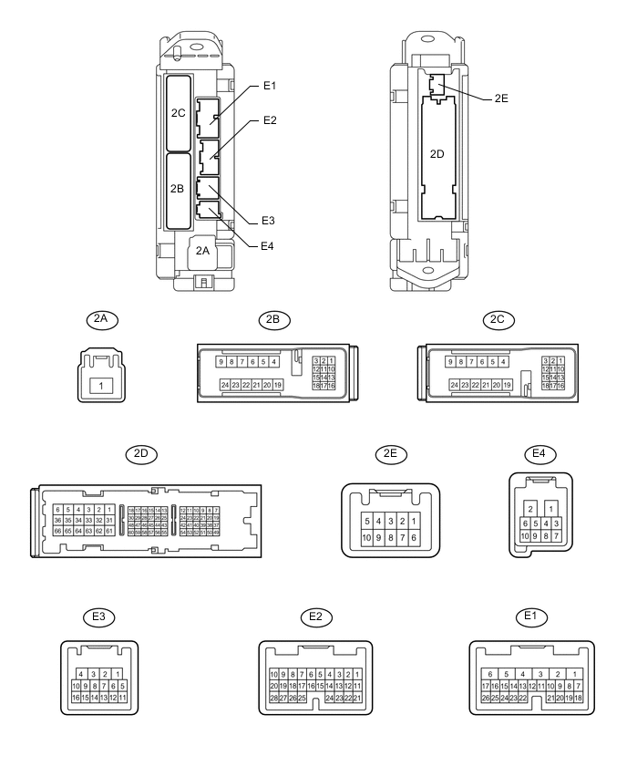
CHECK MAIN BODY ECU (COWL SIDE JUNCTION BLOCK LH)
-
Disconnect the 2D, E1, E2 and E3 ECU connectors.
-
Measure the resistance and voltage according to the value(s) in the table below.
Terminal No. (Symbol) Wiring Color Terminal Description Condition Specified Condition 2D-62 (GND2) - Body ground W-B - Body ground Ground Always Below 1 Ω E3-1 (GND3) - Body ground BR - Body ground Ground Always Below 1 Ω E2-1 (AM2) - 2D-62 (GND2) W - W-B Battery power supply Always 11 to 14 V E1-6 (AM1) - 2D-62 (GND2) W - W-B Battery power supply Always 11 to 14 V If the result is not as specified, there may be a malfunction on the wire harness side.
-
-
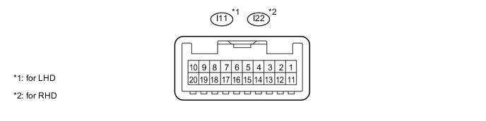
CHECK MASTER SWITCH (for Models with Jam Protection Function on 4 Windows)
-
Disconnect the I11*1 or I22*2 master switch connector.
-
Measure the resistance and voltage according to the value(s) in the table below.
Tech Tips
-
*1: for LHD
-
*2: for RHD
for LHD Terminal No. (Symbol) Wiring Color Terminal Description Condition Specified Condition I11-11 (B) - I11-12 (GND) L - W-B Ignition power supply Ignition switch off Below 1 Ω I11-11 (B) - I11-12 (GND) L - W-B Ignition power supply Ignition switch ON 11 to 14 V I11-12 (GND) - Body ground W-B - Body ground Ground Always Below 1 Ω for RHD Terminal No. (Symbol) Wiring Color Terminal Description Condition Specified Condition I22-11 (B) - I22-12 (GND) L - W-B Ignition power supply Ignition switch off Below 1 Ω I22-11 (B) - I22-12 (GND) L - W-B Ignition power supply Ignition switch ON 11 to 14 V I22-12 (GND) - Body ground W-B - Body ground Ground Always Below 1 Ω If the result is not as specified, there may be a malfunction on the wire harness side.
-
-
-
CHECK FRONT POWER WINDOW REGULATOR MOTOR LH

-
Disconnect the I12 motor connector.
-
Measure the resistance and voltage according to the value(s) in the table below.
Terminal No. (Symbol) Wiring Color Terminal Description Condition Specified Condition I12-2 (B) - I12-1 (GND) L - W-B Battery power supply Always 11 to 14 V I12-1 (GND) - Body ground W-B - Body ground Ground Always Below 1 Ω If the result is not as specified, there may be a malfunction on the wire harness side.
-
-
CHECK FRONT POWER WINDOW REGULATOR MOTOR ASSEMBLY RH

-
Disconnect the I4 motor connector.
-
Measure the resistance and voltage according to the value(s) in the table below.
Terminal No. (Symbol) Wiring Color Terminal Description Condition Specified Condition I4-2 (B) - I4-1 (GND) L - W-B Battery power supply Always 11 to 14 V I4-1 (GND) - Body ground W-B - Body ground Ground Always Below 1 Ω If the result is not as specified, there may be a malfunction on the wire harness side.
-
-
CHECK REAR POWER WINDOW REGULATOR MOTOR ASSEMBLY LH (for Models with Jam Protection Function on 4 Windows)

-
Disconnect the J11 motor connector.
-
Measure the resistance and voltage according to the value(s) in the table below.
Terminal No. (Symbol) Wiring Color Terminal Description Condition Specified Condition J11-2 (B) - J11-1 (GND) L - W-B Battery power supply Always 11 to 14 V J11-1 (GND) - Body ground W-B - Body ground Ground Always Below 1 Ω If the result is not as specified, there may be a malfunction on the wire harness side.
-
-
CHECK REAR POWER WINDOW REGULATOR MOTOR ASSEMBLY RH (for Models with Jam Protection Function on 4 Windows)

-
Disconnect the J4 motor connector.
-
Measure the resistance and voltage according to the value(s) in the table below.
Terminal No. (Symbol) Wiring Color Terminal Description Condition Specified Condition J4-2 (B) - J4-1 (GND) L - W-B Battery power supply Always 11 to 14 V J4-1 (GND) - Body ground W-B - Body ground Ground Always Below 1 Ω If the result is not as specified, there may be a malfunction on the wire harness side.
-
-
CHECK SLIDING ROOF ECU (w/ Sliding Roof System)

-
Disconnect the R5 ECU connector.
-
Measure the resistance and voltage according to the value(s) in the table below.
Terminal No. (Symbol) Wiring Color Terminal Description Condition Specified Condition R5-1 (B) - R5-2 (E) L - W-B Battery power supply Always 11 to 14 V R5-2 (E) - Body ground W-B - Body ground Ground Always Below 1 Ω If the result is not as specified, there may be a malfunction on the wire harness side.
-
-
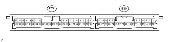
CHECK CERTIFICATION ECU (SMART KEY ECU ASSEMBLY)
-
Disconnect the E29 ECU connector.
-
Measure the resistance and voltage according to the value(s) in the table below.
Terminal No. (Symbol) Wiring Color Terminal Description Condition Specified Condition E29-1 (+B) - E29-17 (E) B - W-B Battery power supply Always 11 to 14 V E29-17 (E) - Body ground W-B - Body ground Ground Always Below 1 Ω If the result is not as specified, there may be a malfunction on the wire harness side.
-
-
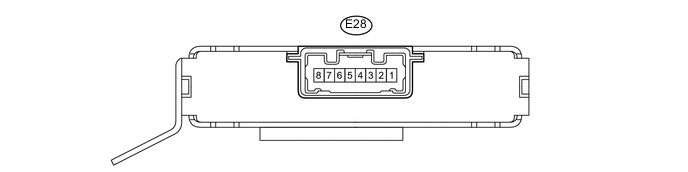
CHECK ID CODE BOX (IMMOBILISER CODE ECU)
-
Disconnect the E28 ECU connector.
-
Measure the resistance and voltage according to the value(s) in the table below.
Terminal No. (Symbol) Wiring Color Terminal Description Condition Specified Condition E28-1 (+B) - E28-8 (GND) B - W-B Battery power supply Always 11 to 14 V E28-8 (GND) - Body ground W-B - Body ground Ground Always Below 1 Ω If the result is not as specified, there may be a malfunction on the wire harness side.
-
-
CHECK STEERING LOCK ECU

-
Disconnect the E26 ECU connector.
-
Measure the resistance and voltage according to the value(s) in the table below.
Terminal No. (Symbol) Wiring Color Terminal Description Condition Specified Condition E26-7 (B) - E26-1 (GND) R - W-B Battery power supply Always 11 to 14 V E26-1 (GND) - Body ground W-B - Body ground Ground Always Below 1 Ω If the result is not as specified, there may be a malfunction on the wire harness side.
-
-
CHECK AIR CONDITIONING AMPLIFIER (for 4-ZONE Type)
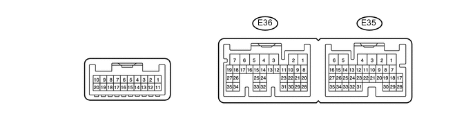
-
Disconnect the E36 amplifier connector.
-
Measure the resistance and voltage according to the value(s) in the table below.
Terminal No. (Symbol) Wiring Color Terminal Description Condition Specified Condition E36-5 (IG+) - E36-1 (GND) G - W-B IG power supply Ignition switch off Below 1 V E36-5 (IG+) - E36-1 (GND) G - W-B IG power supply Ignition switch ON 11 to 14 V E36-6 (+B1) - E36-1 (GND) R - W-B Battery power supply Always 11 to 14 V E36-7 (+B2) - E36-1 (GND) R - W-B Battery power supply Always 11 to 14 V E36-1 (GND) - Body ground W-B - Body ground Ground Always Below 1 Ω If the result is not as specified, there may be a malfunction on the wire harness side.
-
-
CHECK AIR CONDITIONING AMPLIFIER (except 4-ZONE Type)
-
Disconnect the E81 amplifier connector.
-
Measure the resistance and voltage according to the value(s) in the table below.
Terminal No. (Symbol) Wiring Color Terminal Description Condition Specified Condition E81-21 (+B) - E81-14 (GND) R - W-B Battery power supply Always 11 to 14 V E81-1 (IG+) - E81-14 (GND) G - W-B IG power supply Ignition switch ON 11 to 14 V E81-1 (IG+) - E81-14 (GND) G - W-B IG power supply Ignition switch off Below 1 V E81-14 (GND) - Body ground W-B - Body ground Ground Always Below 1 Ω If the result is not as specified, there may be a malfunction on the wire harness side.
-
-
CHECK FRONT AIR CONDITIONING CONTROL PANEL (w/o Navigation System)

-
Disconnect the F10 panel connector.
-
Measure the resistance and voltage according to the value(s) in the table below.
Terminal No. (Symbol) Wiring Color Terminal Description Condition Specified Condition F10-7 (IG+) - F10-1 (GND) G - W-B IG power supply Ignition switch ON 11 to 14 V F10-1 (GND) - Body ground W-B - Body ground Ground Always Below 1 Ω If the result is not as specified, there may be a malfunction on the wire harness side.
-
-
CHECK REAR AIR CONDITIONING CONTROL PANEL
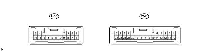
-
Disconnect the E55 panel connector.
-
Measure the resistance and voltage according to the value(s) in the table below.
Terminal No. (Symbol) Wiring Color Terminal Description Condition Specified Condition E55-6 (IG) - E55-1 (E) G - W-B IG power supply Ignition switch ON 11 to 14 V E55-1 (E) - Body ground W-B - Body ground Ground Always Below 1 Ω If the result is not as specified, there may be a malfunction on the wire harness side.
-
-
CHECK RAIN SENSOR (w/ Rain Sensor)

-
Disconnect the R11 rain sensor connector.
-
Measure the voltage according to the value(s) in the table below.
Terminal No. (Symbol) Wiring Color Terminal Description Condition Specified Condition R11-4 (SIG) - Body ground G - Body ground IG signal circuit (to IG relay) Ignition switch off Below 1 V Ignition switch ON 11 to 14 V R11-1 (ES) - Body ground W - Body ground Ground circuit Always Below 1 V If the result is not as specified, there may be a malfunction on the wire harness side.
-
-
CHECK WINDSHIELD WIPER ECU (w/ Rain Sensor)
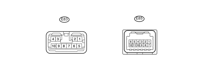
-
Disconnect the E83 and E85 ECU connectors.
-
Measure the voltage and resistance according to the value(s) in the table below.
Terminal No. (Symbol) Wiring Color Terminal Description Condition Specified Condition E83-5 (IG1l) - E83-6 (ES) G - L Power source Ignition switch ON 11 to 14 V E85-10 (E) - Body ground W-B - Body ground Power ground Always Below 1 Ω If the result is not as specified, there may be a malfunction on the wire harness side.
-