FRONT AND SIDE MONITOR MAIN SWITCH INSPECTION
PROCEDURE
-
INSPECT MAIN SWITCH ASSEMBLY
-
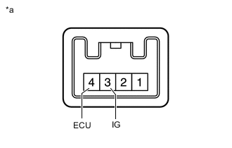
Text in Illustration *1 Component without harness connected
(Main Switch assembly)
Measure the resistance according to the value(s) in the table below.
Standard Resistance Tester Connection Switch Condition Specified Condition 4 (ECU) - 3 (IG) Main switch assembly on Below 1 Ω 4 (ECU) - 3 (IG) Main switch assembly off 10 kΩ or higher If the result is not as specified, replace the main switch assembly .
-