SIDE MONITOR SYSTEM SYSTEM DESCRIPTION
-
GENERAL
-
This system has a side television camera assembly built into the outer rear view mirror assembly (passenger side and driver side) to display the passenger side and driver side views of the vehicle on the multi-display assembly.
-
This system consists of the following components:
-
Outer rear view mirror assembly LH (side television camera assembly)
-
Outer rear view mirror assembly RH (side television camera assembly)
-
Parking assist ECU
-
Multi-media module receiver assembly
-
Multi-display assembly
-
Master cylinder solenoid (skid control ECU assembly)
-
Steering sensor
-
Steering control ECU*
-
Front and side monitor main switch assembly
-
Outer mirror switch assembly
-
Four wheel drive control ECU
-
ECM
-
*: w/ Variable Gear Ratio Steering System
-
-
-
This system is equipped with a self-diagnosis system, which is operated on a designated window that appears on the display panel, just as in the navigation system.
-
-
FUNCTION OF COMPONENTS
-
The parking assist ECU controls the system by using information from the following components.
Item Function Parking Assist ECU
-
Turns the side television camera assembly on or off based on parameters such as the display settings, the front and side monitor main switch signal, the shift signal and the vehicle speed signal.
-
Transmits the wide view front and side monitor, side monitor, or wide view front monitor signals to the multi-media module receiver assembly based on parameters such as the display settings, the front and side monitor main switch signal, the shift signal and the vehicle speed signal.
-
Depending on the display settings, renders the output display for the wide view front and side monitor, the side monitor, or the wide view front monitor, and outputs them to the screen of the multi-display assembly.
-
With the video feed from the side television camera assembly showing the vehicle's left-side surroundings as a base, uses vehicle information such as the signal from the steering angle sensor to calculate and overlay a composite image and output this to the screen of the multi-display.
-
Renders each configuration page in the diagnosis window and outputs the screen to the multi-display assembly.
-
When the outer mirror retraction signal is received, terminates the side camera collimation/alignment.
-
Stores each configuration setting from the diagnosis window.
Multi-media Module Receiver Assembly Communicates with the parking assist ECU through AVC-LAN communication. Multi-display Assembly This touch panel display is used to view and interact with the wide view front and side monitor, side view monitor, wide view front monitor, and diagnosis screens. Side television camera assembly Generates a video feed showing the passenger side of the vehicle and transmits the video to the parking assist ECU. Front and Side Monitor Main Switch Assembly Operating the switch sends a signal to the parking assist ECU. Outer Mirror Switch Assembly Transmits outer mirror retraction signal to parking assist ECU. Steering Sensor Transmits steering angle signal and sensor status signal to multi-display via CAN communication. Steering Control ECU* Sends the VGRS relative angle and vehicle condition to the parking assist ECU through CAN communication. Master Cylinder Solenoid (Skid Control ECU Assembly) Sends the inner brake information and ABS ACT information to the parking assist ECU through CAN communication. Four Wheel Drive Control ECU Sends the L4 condition signal to the parking assist ECU through CAN communication. ECM Sends the vehicle condition, 2WD/4WD information and shift position information to the parking assist ECU through CAN communication.
-
*: w/ Variable Gear Ratio Steering System
-
-
-
DISPLAY CONDITIONS FOR SIDE MONITOR DISPLAY
-
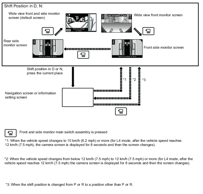
Screen display operation
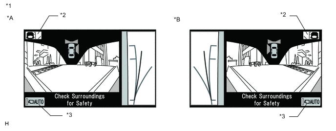
Text in Illustration *A for LHD *B for RHD *1 Wide View Front and Side Monitor Screen *2 Course guideline display change switch *3 Automatic display mode set/cancel switch
(Illustration shows automatic display mode off)
- -
-
After the display conditions are met when the wide view front and side monitor systems are normally functioning, if the screen is changed from the manual display mode or automatic display mode screen, the wide view front and side monitor screen (H4 mode) or wide view front monitor screen (L4 mode) is displayed as the initial screen.
Tech Tips
-
If the shift lever is not in R and the wide view front and side monitor screen is displayed, the course guideline display change switch and automatic display mode set/cancel switch are displayed and the following operations can be performed.
-
For the course guideline display change switch, refer to the below procedures.
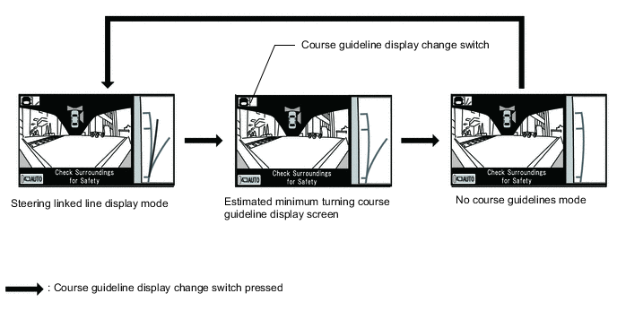
Side Monitor Screen Display Mode Vehicle Width Parallel Lines (Blue) Estimated Minimum Turning Course Guidelines (Blue) Estimated Course Guidelines (Yellow) No course guidelines mode Displayed Not Displayed Not Displayed Estimated minimum turning course guideline display screen Displayed Displayed Not Displayed Steering linked line display mode Displayed Displayed Displayed -
Automatic display mode set/cancel switch
Automatic mode display switch
(Indicator in the button)
Display mode ON
(Illuminated)
Automatic display mode OFF
(Not illuminated)
Manual display mode -
The last mode screen is the screen that was displayed last when the screen was changed to the navigation screen, information setting screen, etc.
-
-
-
Display conditions for manual display mode
-
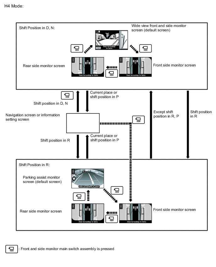
H4 mode:
During manual display mode (shift lever in a position other than R), during engine switch on (IG) or engine startup (no DTCs are output), if the following conditions have been met, pressing the front and side monitor main switch will change the display mode as follows
Automatic Mode Display Switch Multi-display Screen Shift Lever Position Vehicle Speed Screen
(changes due to front and side monitor main switch assembly operation)
OFF Navigation screen or information setting screen Other than R 12 km/h (7.5 mph) or less Navigation screen or information setting screen → Wide view front and side monitor screen → Front side monitor screen → Rear side monitor screen → Wide view front and side monitor screen R position 0 km/h (0 mph) Navigation screen or information setting screen → Parking assist monitor screen → Wide view front and side monitor screen → Front side monitor screen → Rear side monitor screen → Parking assist monitor screen -
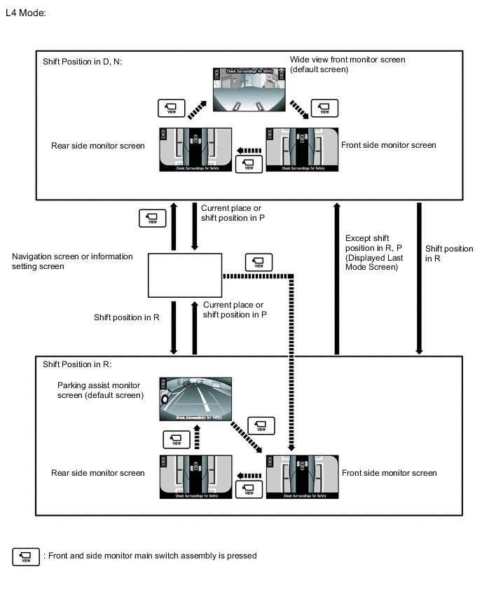
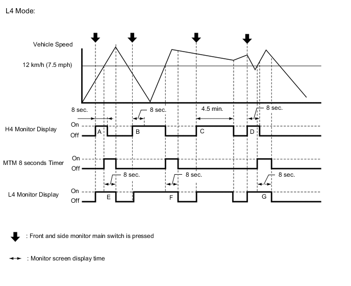
L4 mode:
In manual display mode, when the following conditions are met with the engine switch on (IG) or the engine started (no DTCs are output), the screen display can be changed by pressing the front and side monitor main switch assembly.
Automatic Mode Display Switch Multi-display Screen Shift Lever Position Vehicle Speed Screen
(changes due to front and side monitor main switch assembly operation)
OFF Navigation screen or information setting screen Other than R 12 km/h (7.5 mph) or less Navigation screen or information setting screen → Wide view front monitor screen → Front side monitor screen → Rear side monitor screen → Wide view front monitor screen R position 0 km/h (0 mph) Navigation screen or information setting screen → Parking assist monitor screen → Wide view front and side monitor screen → Front side monitor screen → Rear side monitor screen → Parking assist monitor screen
-
-
Screen display timer function
-
During manual display mode (when the shift lever is not in R), when the front and side monitor main switch is pressed and the following conditions are met, the wide view front and side monitor screen is displayed for a certain period of time even when the vehicle speed is more than 12 km/h (7.5 mph).
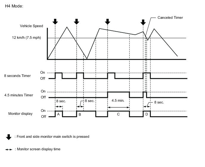
Screen Display Time Time when Front and Side Monitor Main Switch Assembly is Pressed Change in Vehicle Speed Timer Operation Time Note A
B
12 km/h (7.5 mph) or less 12 km/h (7.5 mph) or less 8 seconds When the front and side monitor main switch assembly is pressed with the vehicle speed at 12 km/h (7.5 mph) or less, the camera screen is displayed for 8 seconds from the moment the switch is pressed. After this, if the vehicle speed increases to above 12 km/h (7.5 mph), the camera screen is not displayed. C More than 12 km/h (7.5 mph) More than 12 km/h (7.5 mph) 8 seconds or 4 minutes and 30 seconds When the front and side monitor main switch assembly is pressed while the vehicle speed is more than 12 km/h (7.5 mph), the camera screen is displayed for 4 minutes and 30 seconds the moment the switch is pressed (when the vehicle speed is more than 12 km/h (7.5 mph) after 4 minutes and 30 seconds elapse from the time the switch is pressed). D More than 12 km/h (7.5 mph) More than 12 km/h (7.5 mph) → 12 km/h (7.5 mph) or less → More than 12 km/h (7.5 mph) 8 seconds or 4 minutes and 30 seconds When the front and side monitor main switch assembly is pressed while the vehicle speed is more than 12 km/h (7.5 mph), the screen display timer operates and the camera screen is displayed. However, after the vehicle speed decreases to 12 km/h (7.5 mph) or less within 4 minutes and 30 seconds (after 8 seconds have elapsed), if the vehicle speed increases to more than 12 km/h (7.5 mph) again, the screen switches to the navigation or information setting screen.
After the vehicle speed decreases to 12 km/h (7.5 mph) or less within 8 seconds, if the vehicle speed increases to more than 12 km/h (7.5 mph) again, the 4 minutes 30 seconds timer is canceled and the camera screen is displayed for 8 seconds the moment the front and side monitor main switch assembly is pressed.
E
F
G
More than 12 km/h (7.5 mph) More than 12 km/h (7.5 mph) 8 seconds If the vehicle speed is more than 12 km/h (7.5 mph), the camera screen is displayed for 8 seconds. After that, the camera screen is not displayed. The timer is canceled the moment the vehicle speed decreases to below 12 km/h (7.5 mph) during the 8 second timer.
-
-
Display conditions for automatic display mode
-
In automatic display mode, the screen display is automatically displayed according to driving conditions when the following conditions are met and the wide view front and side monitor systems are normally operating.
Vehicle Condition Multi-display Assembly Display Screen Shift Lever Vehicle Speed Display Screen Stopped → Driving Navigation screen or information setting screen Not in P or R 12 km/h (7.5 mph) or less Navigation screen or information setting screen → Wide view front monitor and side monitor screen* Driving → Stopped Not in P or R 10 km/h (6.2 mph) or less Navigation screen or information setting screen → Wide view front monitor and side monitor screen*
-
*:The conditions to change the screen after the display screen changes automatically are the same as in manual display mode.
-
-
-
Off-road turn assist function
-
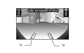
Text in Illustration *a Line Indicating Travel Path With the off-road turn assist function on, the path traveled is displayed as dotted lines on the front screen. In this state, the vehicle may not move exactly as the front lines indicate. (The lines indicate the direction the front wheels are turned. However, with the off-road assist function on, the vehicle turns using a difference in drive force between the left and right wheels.)
-
-
-
OPERATION EXPLANATION
-
The front and side monitor main switch ON signal is sent from the main switch to the parking assist ECU.
After receiving the front and side monitor main switch ON signal, the parking assist ECU switches the display signal for the display and navigation module display from the navigation system to the side monitor system.
-
-
COMMUNICATION SYSTEM OUTLINE
-
The components of the side monitor system communicate with each other through the AVC-LAN. If a short circuit or open circuit occurs in the AVC-LAN, communication is interrupted and the side monitor system will stop functioning.
-
-
DIAGNOSTIC FUNCTION OUTLINE
-
This side monitor system has a diagnostic function displayed in the parking assist ECU. This function enables the calibration (adjustment and confirmation) of the system Click here.
-
The system can check the following items by using the intelligent tester.
Item Proceed to DTC
-