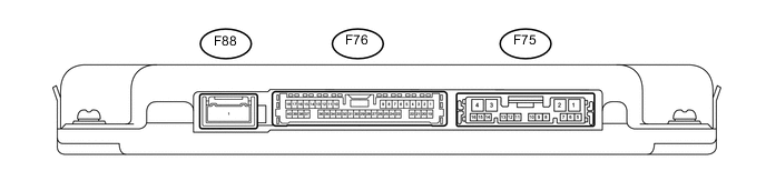
WIDE VIEW FRONT MONITOR SYSTEM TERMINALS OF ECU
-
PARKING ASSIST ECU
-
Disconnect the F75 and F76 parking assist ECU connectors.
-
Measure the voltage and resistance according to the value(s) in the table below.
Terminal No. (Symbol) Wiring Color Terminal Description Condition Specified Condition F75-1 (+B) - F75-4 (GND1) L - W-B Power source signal Always 11 to 14 V F75-4 (GND1) - Body ground W-B - Body ground Ground Always Below 1 Ω F75-8 (IG) - F75-4 (GND1) G - W-B IG Power source signal Engine switch on (IG) 11 to 14 V Engine switch off Below 1 V F75-9 (ACC) - F75-4 (GND1) GR - W-B ACC Power source signal Engine switch on (ACC) 11 to 14 V Engine switch off Below 1 V F76-7 (BLSW) - F75-4 (GND1) G - W-B Front and side monitor main switch power source signal Engine switch on (IG), front and side monitor main switch assembly on 11 to 14 V -
Reconnect the F75 and F76 parking assist ECU connectors.
-
Measure the voltage according to the value(s) in the table below.
Terminal No. (Symbol) Wiring Color Terminal Description Condition Specified Condition F75-10 (TX-) L AVC-LAN communication signal - - F75-11 (TX+) W AVC-LAN communication signal - - F76-36 (BCV-) - F76-35 (BGND) W - Shielded Front television camera ground Always Below 1 V F76-12 (BCV+) - F76-35 (BGND) R - Shielded Front television camera display signal input Engine switch on (IG), front and side monitor main switch assembly on Pulse generation (See waveform) F76-35 (BGND) - F75-4 (GND1) Shielded - W-B Front television camera ground (shield) Always Below 1 V F76-11 (BCB+) - F76-35 (BGND) B - Shielded Power source to front television camera Engine switch on (IG), front and side monitor main switch assembly on 5.5 to 7.05 V -
Using an oscilloscope, check waveform.
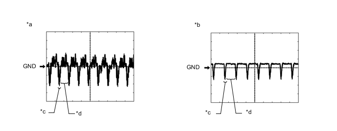
Text in Illustration *a Waveform A (under normal conditions) *b Waveform B (camera lens is covered, blacking out the screen) *c Synchronized Signal *d Video Waveform Tech Tips
The video waveform changes according to the image sent by the rear television camera assembly.
-
Waveform
Item Content Terminal No. (Symbol) F76-12 (BCV+) - F76-35 (BGND) Tool Setting 200 mV/DIV., 50 μsec./DIV. Condition
-
Waveform A: Engine switch on (IG), front and side monitor main switch assembly on and camera lens is not covered, displaying an image
-
Waveform B: Engine switch on (IG), front and side monitor main switch assembly on and camera lens is covered, blacking out the screen.
-
-
-
-
FRONT TELEVISION CAMERA ASSEMBLY

-
Disconnect the A55 front television camera assembly connector.
-
Measure the voltage according to the value(s) in the table below.
Terminal No. (Symbol) Wiring Color Terminal Description Condition Specified Condition A55-3 (BGND) - Body ground BR - Body ground Ground Always Below 1 V A55-1 (BCB+) - A55-3 (BGND) G - BR Power source Engine switch on (IG)
Front and side monitor main switch on
5.5 to 7.05 V -
Reconnect the A55 front television camera assembly connector.
Tech Tips
A waterproof connector is used for the front television camera assembly. Therefore, inspect the waveform at the parking assist ECU with the connector connected.
-
Measure the voltage according to the value(s) in the table below.
Terminal No. (Symbol) Wiring Color Terminal Description Condition Specified Condition A55-2 (BCV+) - A55-3 (BGND) L -BR Display signal Engine switch on (IG), front and side monitor main switch assembly on Pulse generation (See waveform) A55-4 (BCV-) - A55-3 (BGND) Y -BR Front television camera ground Always Below 1 V -
Using an oscilloscope, check waveform.
Text in Illustration *a Waveform A (under normal conditions) *b Waveform B (camera lens is covered, blacking out the screen) *c Synchronized Signal *d Video Waveform Tech Tips
The video waveform changes according to the image sent by the front television camera assembly.
-
Waveform
Item Content Terminal No. (Symbol) A55-2 (BCV+) - A55-3 (BGND) Tool Setting 200 mV/DIV., 50 μsec./DIV. Condition
-
Waveform A: Engine switch on (IG), front and side monitor main switch assembly on and camera lens is not covered, displaying an image
-
Waveform B: Engine switch on (IG), front and side monitor main switch assembly on and camera lens is covered, blacking out the screen.
-
-
-
-
MULTI-MEDIA MODULE RECEIVER ASSEMBLY Click here
-
MULTI-DISPLAY ASSEMBLY Click here