PARKING ASSIST MONITOR SYSTEM(w/o Side Monitor System), Diagnostic DTC:C1622
| DTC Code | DTC Name |
|---|---|
| C1622 | Back Camera Disconnected |
DESCRIPTION
This DTC is stored if the multi-media module receiver assembly judges that the signals or signal lines between the multi-media module receiver assembly and the rear television camera assembly are not normal as a result of its self check.
| DTC Code | DTC Detection Condition | Trouble Area |
|---|---|---|
| C1622 | Open or short in the rear television camera assembly signal circuit |
|
WIRING DIAGRAM
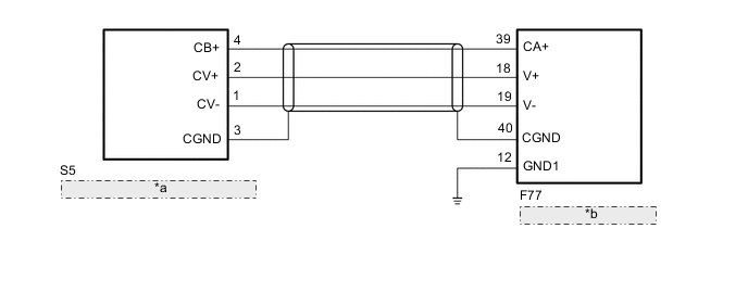
| *a | Rear Television Camera Assembly |
| *b | Multi-media Module Receiver Assembly |
CAUTION / NOTICE / HINT
Note
-
When "System initializing" is displayed on the multi-media module receiver assembly after disconnecting the cable from the negative (-) battery terminal, correct the steering angle neutral point Click here.
-
Depending on the parts that are replaced or operations that are performed during vehicle inspection or maintenance, calibration of other systems as well as the parking assist monitor system (w/o Side Monitor System) may be needed Click here.
PROCEDURE
-
CHECK HARNESS AND CONNECTOR (MULTI-MEDIA MODULE RECEIVER - REAR TELEVISION CAMERA AND BODY GROUND)
-
Disconnect the F77 multi-media module receiver assembly connector.
-
Disconnect the S5 rear television camera assembly connector.
-
Measure the resistance according to the value(s) in the table below.
Standard Resistance Tester Connection Condition Specified Condition F77-18 (V+) - S5-2 (CV+) Always Below 1 Ω F77-19 (V-) - S5-1 (CV-) Always Below 1 Ω F77-39 (CA+) - S5-4 (CB+) Always Below 1 Ω F77-40 (CGND) - S5-3 (CGND) Always Below 1 Ω F77-12 (GND1) - Body ground Always Below 1 Ω F77-18 (V+) - Body ground Always 10 kΩ or higher F77-19 (V-) - Body ground Always 10 kΩ or higher F77-39 (CA+) - Body ground Always 10 kΩ or higher F77-40 (CGND) - Body ground Always 10 kΩ or higher
NG 
REPAIR OR REPLACE HARNESS OR CONNECTOR
OK 
-
-
CHECK MULTI-MEDIA MODULE RECEIVER ASSEMBLY (CA+, CGND)
-
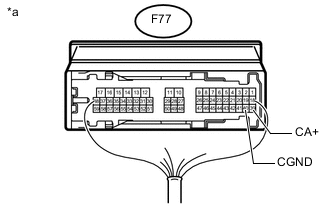
Text in Illustration *a Component with harness connected
(Multi-media Module Receiver Assembly)
Reconnect the multi-media module receiver assembly connector.
-
Measure the resistance according to the value(s) in the table below.
Standard Resistance Tester Connection Condition Specified Condition F77-40 (CGND) - Body ground Always Below 1 Ω -
Measure the voltage according to the value(s) in the table below.
Standard Voltage Tester Connection Condition Specified Condition F77-39 (CA+) - F77-40 (CGND) Engine switch on (IG), shift lever in R 5.5 to 7.05 V
NG
REPLACE MULTI-MEDIA MODULE RECEIVER ASSEMBLY Click here
OK
-
-
CHECK REAR TELEVISION CAMERA ASSEMBLY (CV+, CGND)
-
Reconnect the S5 rear television camera assembly connector.
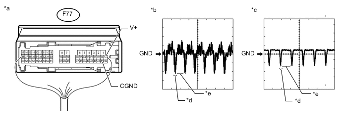
Text in Illustration *a Component with harness connected
(Multi-media Module Receiver Assembly)
*b Waveform A *c Waveform A *d Synchronization Signal *e Video Waveform - - -
Check the waveform of the rear television camera assembly using an oscilloscope.
Tech Tips
-
A waterproof connector is used for the rear television camera assembly. Therefore, inspect the waveform at the multi-media module receiver assembly with the connector connected.
-
The video waveform changes according to the image sent by the rear television camera assembly.
Measurement Condition Item Content Tester No. (Symbol) F77-18 (V+) - F77-40 (CGND) Tool Setting 0.2 V/DIV., 50 μS/DIV Condition Waveform A: Engine starts, shift lever in R (camera lens is not covered, displaying an image)
Waveform B: Engine starts, shift lever in R (camera lens is covered, blacking out the screen)
OK Waveform is as shown in the illustration. -
OK
REPLACE MULTI-MEDIA MODULE RECEIVER ASSEMBLY Click here
NG
REPLACE REAR TELEVISION CAMERA ASSEMBLY Click here
-