TOYOTA PARKING ASSIST-SENSOR SYSTEM Clearance Warning Buzzer Circuit
DESCRIPTION
The No. 1 clearance warning buzzer sounds to alert the driver and the buzzed frequency changes depending on the distance to an obstacle.
WIRING DIAGRAM
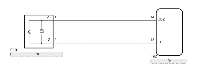
| *a | No. 1 Clearance Warning Buzzer |
| *b | Clearance Warning ECU Assembly |
PROCEDURE
-
PERFORM ACTIVE TEST USING GTS (NO. 1 CLEARANCE WARNING BUZZER)
-
Select the Active Test, use the GTS to generate a control command, and then check that the buzzer operates Click here.
Clearance Sonar Tester Display Test Part Control Range Diagnostic Note Front Buzzer No. 1 clearance warning buzzer Operate or Stop - OK No. 1 clearance warning buzzer sounds.
OK 
PROCEED TO NEXT CIRCUIT INSPECTION SHOWN IN PROBLEM SYMPTOMS TABLE Click here
NG 
-
-
CHECK HARNESS AND CONNECTOR (CLEARANCE WARNING ECU ASSEMBLY - NO. 1 CLEARANCE WARNING BUZZER)
-
Disconnect the F92 clearance warning ECU assembly connector.
-
Disconnect the E10 No. 1 clearance warning buzzer connector.
-
Measure the resistance according to the value(s) in the table below.
Standard Resistance Tester Connection Condition Specified Condition F92-14 (BBZ) - E10-1 (Z+) Always Below 1 Ω F92-13 (EF) - E10-2 (Z-) Always Below 1 Ω F92-14 (BBZ) - Body ground Always 10 kΩ or higher F92-13 (EF) - Body ground Always 10 kΩ or higher
OK
REPLACE NO. 1 CLEARANCE WARNING BUZZER Click here
NG
REPAIR OR REPLACE HARNESS OR CONNECTOR
-