CAN COMMUNICATION SYSTEM(for LHD without Central Gateway ECU) TERMINALS OF ECU
Note
-
After turning the ignition switch off, waiting time may be required before disconnecting the cable from the negative (-) battery terminal. Therefore, make sure to read the disconnecting the cable from the negative (-) battery terminal notices before proceeding with work Click here.
-
Turn the ignition switch off before measuring the resistances between CAN main wires and between CAN branch wires.
-
Turn the ignition switch off before inspecting CAN wires for a ground short.
-
Before measuring the resistance of the CAN bus, turn the ignition switch off and leave the vehicle for 1 minute or more without operating the key, switches or opening or closing the doors. After that, disconnect the cable from the negative (-) battery terminal and leave the vehicle for 1 minute or more before measuring the resistance.
-
This section describes the standard values for all CAN related components.
Tech Tips
-
Operating the ignition switch, any other switches or a door triggers related ECU and sensor communication on the CAN. This communication will cause the resistance value to change.
-
Even after DTCs are cleared, if a DTC is stored again after driving the vehicle for a while, the malfunction may be occurring due to vibration of the vehicle. In such a case, wiggling the ECUs or wire harness while performing the inspection below may help determine the cause of the malfunction.
-
JUNCTION CONNECTOR
-
NO. 1 CAN JUNCTION CONNECTOR
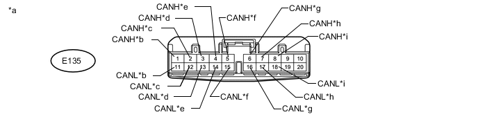
Text in Illustration *a Front view of wire harness connector
(to No. 1 CAN Junction Connector)
*b for No. 2 CAN Junction Connector *c for 4WD Control ECU *d for Power Steering ECU Assembly (w/ Variable Flow Control Solenoid Valve) *e for Airbag Sensor Assembly *f for Tire Pressure Warning ECU (w/ Tire Pressure Warning System) *g for Bus Buffer ECU (w/ Bus Buffer ECU) *h for ECM *i for Air Conditioning Amplifier Assembly - - No. 1 CAN Junction Connector Wiring Color Connect to E135-1 (CANH) SB No. 2 CAN junction connector E135-11 (CANL) W E135-2 (CANH) P 4WD control ECU E135-12 (CANL) W E135-3 (CANH) LG Power steering ECU assembly*1 E135-13 (CANL) W E135-4 (CANH) GR Airbag sensor assembly E135-14 (CANL) W E135-5 (CANH) R Tire pressure warning ECU*2 E135-15 (CANL) W E135-6 (CANH) BE Bus buffer ECU*3 E135-16 (CANL) W E135-7 (CANH) V ECM E135-17 (CANL) W E135-8 (CANH) G Air conditioning amplifier assembly E135-18 (CANL) W
-
*1: w/ Variable Flow Control Solenoid Valve
-
*2: w/ Tire Pressure Warning System
-
*3: w/ Bus Buffer ECU
-
-
NO. 2 CAN JUNCTION CONNECTOR
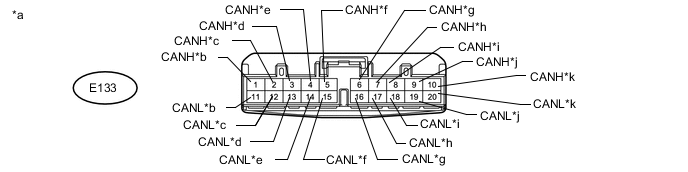
Text in Illustration *a Front view of wire harness connector
(to No. 2 CAN Junction Connector)
*b for No. 1 CAN Junction Connector *c for Main Body ECU (Multiplex Network Body ECU) *d for Master Cylinder Solenoid (Skid Control ECU) *e for Headlight Leveling ECU Assembly *f
-
for Multi-media Module Receiver Assembly (for Multi-media Module Receiver Type)
-
for Radio and Display Receiver Assembly (for Radio and Display Type)
*g for Certification ECU (Smart Key ECU Assembly) (w/ Entry and Start System) *h for Combination Meter Assembly *i for Steering control ECU (w/ Variable Gear Ratio Steering System) *j for DLC3 *k for Spiral with Sensor Cable Sub-assembly (Steering Angle Sensor) - - No. 2 CAN Junction Connector Wiring Color Connect to E133-1 (CANH) SB No. 1 CAN junction connector E133-11 (CANL) W E133-2 (CANH) G Main body ECU (multiplex network body ECU) E133-12 (CANL) W E133-3 (CANH) L Master cylinder solenoid (skid control ECU) E133-13 (CANL) W E133-4 (CANH) LG Headlight leveling ECU assembly E133-14 (CANL) B E133-5 (CANH) G
-
Multi-media module receiver assembly*1
-
Radio and display receiver assembly*2
E133-15 (CANL) GR E133-6 (CANH) B Certification ECU (smart key ECU assembly)*3 E133-16 (CANL) W E133-7 (CANH) BE Combination meter assembly E133-17 (CANL) W E133-8 (CANH) R Steering control ECU*4 E133-18 (CANL) W E133-9 (CANH) LG DLC3 E133-19 (CANL) W E133-10 (CANH) GR Spiral with sensor cable sub-assembly (steering angle sensor) E133-20 (CANL) W
-
*1: for Multi-media Module Receiver Type
-
*2: for Radio and Display Type
-
*3: w/ Entry and Start System
-
*4: w/ Variable Gear Ratio Steering System
-
-
NO. 7 CAN JUNCTION CONNECTOR
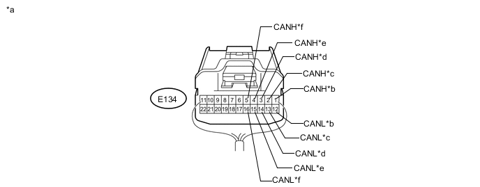
Text in Illustration *a Rear view of wire harness connector
(to No. 7 CAN Junction Connector)
*b for No. 8 CAN Junction Connector *c for Main Body ECU (Multiplex Network Body ECU) *d for Outer Mirror Control ECU Assembly LH (w/ Memory) *e for Power Seat Switch Assembly (w/ Memory) *f for Multiplex Tilt and Telescopic ECU (w/ Power Tilt and Power Telescopic Steering Column System) No. 7 CAN Junction Connector Wiring Color Connect to E134-1 (CANH) W No. 8 CAN junction connector E134-12 (CANL) L E134-2 (CANH) GR Main body ECU (multiplex network body ECU) E134-13 (CANL) L E134-3 (CANH) BE Outer mirror control ECU assembly LH*1 E134-14 (CANL) L E134-4 (CANH) V Power seat switch assembly*1 E134-15 (CANL) L E134-5 (CANH) P Multiplex Tilt and Telescopic ECU*2 E134-16 (CANL) L
-
*1: w/ Memory
-
*2: w/ Power Tilt and Power Telescopic Steering Column System
-
-
NO. 8 CAN JUNCTION CONNECTOR
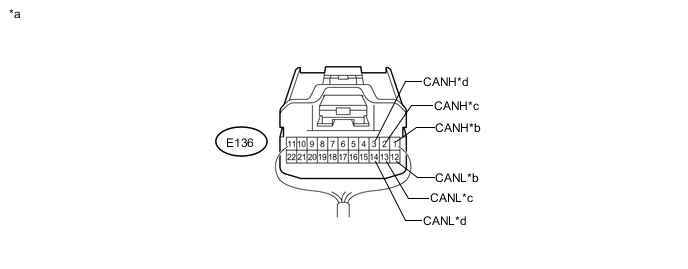
Text in Illustration *a Rear view of wire harness connector
(to No. 8 CAN Junction Connector)
*b for No. 7 CAN Junction Connector *c for No. 9 CAN Junction Connector *d for Outer Mirror Control ECU Assembly RH (w/ Memory) No. 8 CAN Junction Connector Wiring Color Connect to E136-1 (CANH) W No. 7 CAN junction connector E136-12 (CANL) L E136-2 (CANH) W No. 9 CAN junction connector E136-13 (CANL) L E136-3 (CANH) LG Outer mirror control ECU assembly RH* E136-14 (CANL) L
-
*: w/ Memory
-
-
NO. 9 CAN JUNCTION CONNECTOR
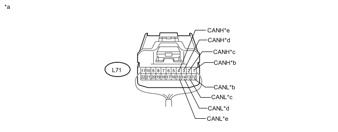
Text in Illustration *a Rear view of wire harness connector
(to No. 9 CAN Junction Connector)
*b for No. 8 CAN Junction Connector *c No. 3 CAN Junction Terminal *d for Power Back Door Unit Assembly (Power Back Door ECU) (w/ Power Back Door System) *e for No. 2 Main Body ECU (w/ Tail Gate Closer System) - - No. 9 CAN Junction Connector Wiring Color Connect to L71-1 (CANH) W No. 8 CAN junction connector L71-12 (CANL) L L71-2 (CANH) W No. 3 CAN junction terminal L71-13 (CANL) L L71-3 (CANH) V Power back door unit assembly (power back door ECU)*1 L71-14 (CANL) L L71-4 (CANH) LG No. 2 main body ECU*2 L71-15 (CANL) L
-
*1: w/ Power Back Door System
-
*2: w/ Tail Gate Closer System
-
-
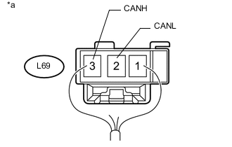
Text in Illustration *a Rear view of wire harness connector
(to No. 3 CAN Junction Terminal)
NO. 3 CAN JUNCTION TERMINAL
No. 3 CAN Junction Terminal Wiring Color Connect to L69-3 (CANH) W No. 9 CAN junction connector L69-2 (CANL) L
-
-
CHECK DLC3
-
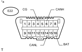
Text in Illustration *a Front view of DLC3 Disconnect the cable from the negative (-) battery terminal before measuring the resistances of the CAN main wire and CAN branch wire.
-
Measure the resistance according to the value(s) in the table below.
Terminal No. (Symbol) Wiring Color Switch Condition Specified Condition E22-6 (CANH) - E22-14 (CANL) LG - W Cable disconnected from negative (-) battery terminal 54 to 69 Ω E22-6 (CANH) - E22-4 (CG) LG - W-B Cable disconnected from negative (-) battery terminal 200 Ω or higher E22-14 (CANL) - E22-4 (CG) W - W-B Cable disconnected from negative (-) battery terminal 200 Ω or higher E22-6 (CANH) - E22-16 (BAT) LG - L Cable disconnected from negative (-) battery terminal 6 kΩ or higher E22-14 (CANL) - E22-16 (BAT) W - L Cable disconnected from negative (-) battery terminal 6 kΩ or higher
-
-
CHECK ECM
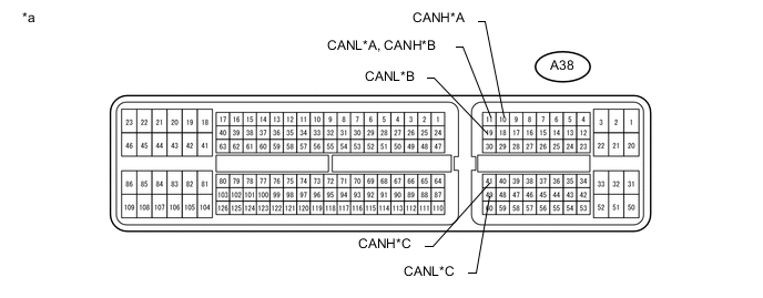
Text in Illustration *A for 1UR-FE, 1GR-FE *B for 3UR-FE *C for 1VD-FTV - - *a Component without harness connected
(ECM)
- -
-
Disconnect the ECM connectors.
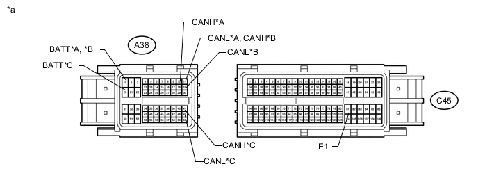
Text in Illustration *A for 1UR-FE, 1GR-FE *B for 3UR-FE *C for 1VD-FTV - - *a Front view of wire harness connector
(to ECM)
- - -
Measure the resistance according to the value(s) in the table below.
for 1UR-FE, 1GR-FE Terminal No. (Symbol) Wiring Color Switch Condition Specified Condition A38-10 (CANH) - A38-11 (CANL) V - W Cable disconnected from negative (-) battery terminal 108 to 132 Ω A38-10 (CANH) - C45-81 (E1) V - BR Cable disconnected from negative (-) battery terminal 200 Ω or higher A38-11 (CANL) - C45-81 (E1) W - BR Cable disconnected from negative (-) battery terminal 200 Ω or higher A38-10 (CANH) - A38-1 (BATT) V - L Cable disconnected from negative (-) battery terminal 6 kΩ or higher A38-11 (CANL) - A38-1 (BATT) W - L Cable disconnected from negative (-) battery terminal 6 kΩ or higher for 3UR-FE Terminal No. (Symbol) Wiring Color Switch Condition Specified Condition A38-11 (CANH) - A38-19 (CANL) V - W Cable disconnected from negative (-) battery terminal 108 to 132 Ω A38-11 (CANH) - C45-81 (E1) V - W-B Cable disconnected from negative (-) battery terminal 200 Ω or higher A38-19 (CANL) - C45-81 (E1) W - W-B Cable disconnected from negative (-) battery terminal 200 Ω or higher A38-11 (CANH) - A38-1 (BATT) V - L Cable disconnected from negative (-) battery terminal 6 kΩ or higher A38-19 (CANL) - A38-1 (BATT) W - L Cable disconnected from negative (-) battery terminal 6 kΩ or higher for 1VD-FTV Terminal No. (Symbol) Wiring Color Switch Condition Specified Condition A38-41 (CANH) - A38-49 (CANL) V - W Cable disconnected from negative (-) battery terminal 108 to 132 Ω A38-41 (CANH) - C45-81 (E1) V - BR Cable disconnected from negative (-) battery terminal 200 Ω or higher A38-49 (CANL) - C45-81 (E1) W - BR Cable disconnected from negative (-) battery terminal 200 Ω or higher A38-41 (CANH) - A38-20 (BATT) V - L Cable disconnected from negative (-) battery terminal 6 kΩ or higher A38-49 (CANL) - A38-20 (BATT) W - L Cable disconnected from negative (-) battery terminal 6 kΩ or higher
-
-
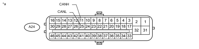
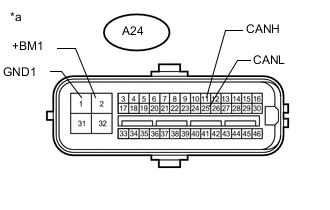
CHECK MASTER CYLINDER SOLENOID (SKID CONTROL ECU)
Text in Illustration *a Component without harness connected
(Master Cylinder Solenoid [Skid Control ECU])
- -
-
Text in Illustration *a Front view of wire harness connector
(to Master Cylinder Solenoid [Skid Control ECU])
Disconnect the master cylinder solenoid (skid control ECU) connector.
-
Measure the resistance according to the value(s) in the table below.
Terminal No. (Symbol) Wiring Color Switch Condition Specified Condition A24-11 (CANH) - A24-25 (CANL) L - W Cable disconnected from negative (-) battery terminal 54 to 69 Ω A24-11 (CANH) - A24-1 (GND1) L - W-B Cable disconnected from negative (-) battery terminal 200 Ω or higher A24-25 (CANL) - A24-1 (GND1) W - W-B Cable disconnected from negative (-) battery terminal 200 Ω or higher A24-11 (CANH) - A24-2 (+BM1) L - B Cable disconnected from negative (-) battery terminal 6 kΩ or higher A24-25 (CANL) - A24-2 (+BM1) W - B Cable disconnected from negative (-) battery terminal 6 kΩ or higher
-
-
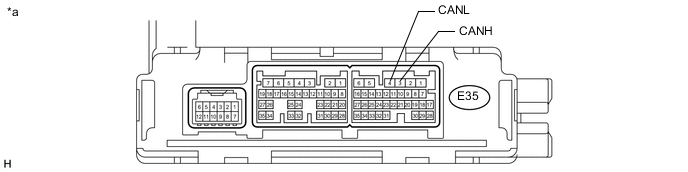
CHECK AIR CONDITIONING AMPLIFIER ASSEMBLY (for Automatic Air Conditioning System)
Text in Illustration *a Component without harness connected
(Air Conditioning Amplifier Assembly)
- -
-
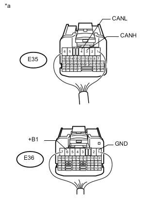
Text in Illustration *a Rear view of wire harness connector
(to Air Conditioning Amplifier Assembly)
Disconnect the air conditioning amplifier assembly connectors.
-
Measure the resistance according to the value(s) in the table below.
Terminal No. (Symbol) Wiring Color Condition Specified Condition E35-3 (CANH) - E35-4 (CANL) G - W Cable disconnected from negative (-) battery terminal 54 to 69 Ω E35-3 (CANH) - E36-1 (GND) G - BR Cable disconnected from negative (-) battery terminal 200 Ω or higher E35-4 (CANL) - E36-1 (GND) W - BR Cable disconnected from negative (-) battery terminal 200 Ω or higher E35-3 (CANH) - E36-6 (+B1) G - LG Cable disconnected from negative (-) battery terminal 6 kΩ or higher E35-4 (CANL) - E36-6 (+B1) W - LG Cable disconnected from negative (-) battery terminal 6 kΩ or higher
-
-
CHECK AIR CONDITIONING AMPLIFIER ASSEMBLY (for Manual Air Conditioning System)
Text in Illustration *a Component without harness connected
(Air Conditioning Amplifier Assembly)
- -
-
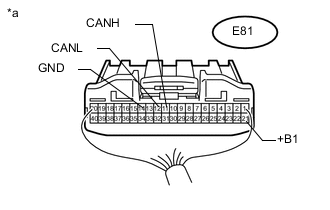
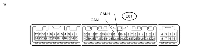
Text in Illustration *a Rear view of wire harness connector
(to Air Conditioning Amplifier Assembly)
Disconnect the air conditioning amplifier assembly connector.
-
Measure the resistance according to the value(s) in the table below.
Terminal No. (Symbol) Wiring Color Condition Specified Condition E81-11 (CANH) - E81-12 (CANL) G - W Cable disconnected from negative (-) battery terminal 54 to 69 Ω E81-11 (CANH) - E81-14 (GND) G - BR Cable disconnected from negative (-) battery terminal 200 Ω or higher E81-12 (CANL) - E81-14 (GND) W - BR Cable disconnected from negative (-) battery terminal 200 Ω or higher E81-11 (CANH) - E81-21 (+B1) G - LG Cable disconnected from negative (-) battery terminal 6 kΩ or higher E81-12 (CANL) - E81-21 (+B1) W - LG Cable disconnected from negative (-) battery terminal 6 kΩ or higher
-
-
CHECK COWL SIDE JUNCTION BLOCK LH AND MAIN BODY ECU (MULTIPLEX NETWORK BODY ECU)
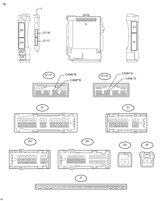
Text in Illustration *A Main Body ECU (Multiplex Network Body ECU) with 2 Connectors *B Bus 2 *C Sub Bus 1 - - *1 Main Body ECU (Multiplex Network Body ECU) - - 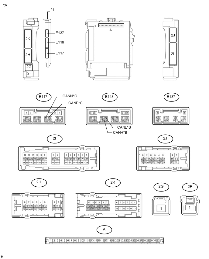
Text in Illustration *A Main Body ECU (Multiplex Network Body ECU) with 3 Connectors *B Bus 2 *C Sub Bus 1 - - *1 Main Body ECU (Multiplex Network Body ECU) - -
-
Remove the main body ECU (multiplex network body ECU) from the cowl side junction block LH Click here.
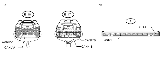
Text in Illustration *A Bus 2 *B Sub Bus 1 *a Rear view of wire harness connector
(to Main Body ECU [Multiplex Network Body ECU])
*b Front view of wire harness connector
(to Main Body ECU [Multiplex Network Body ECU])
-
Reconnect the cowl side junction block LH connectors.
-
Measure the resistance according to the value(s) in the table below.
Bus 2 Terminal No. (Symbol) Wiring Color Switch Condition Specified Condition E118-14 (CANH) - E118-13 (CANL) G - W Cable disconnected from negative (-) battery terminal 54 to 69 Ω E118-14 (CANH) - A-11 (GND1) G - None Cable disconnected from negative (-) battery terminal 200 Ω or higher E118-13 (CANL) - A-11 (GND1) W - None Cable disconnected from negative (-) battery terminal 200 Ω or higher E118-14 (CANH) - A-31 (BECU) G - None Cable disconnected from negative (-) battery terminal 6 kΩ or higher E118-13 (CANL) - A-31 (BECU) W - None Cable disconnected from negative (-) battery terminal 6 kΩ or higher Sub Bus 1 Terminal No. (Symbol) Wiring Color Switch Condition Specified Condition E117-9 (CANP) - E117-10 (CANN) GR - L Cable disconnected from negative (-) battery terminal 108 to 132 Ω E117-9 (CANP) - A-11 (GND1) GR - None Cable disconnected from negative (-) battery terminal 200 Ω or higher E117-10 (CANN) - A-11 (GND1) L - None Cable disconnected from negative (-) battery terminal 200 Ω or higher E117-9 (CANP) - A-31 (BECU) GR - None Cable disconnected from negative (-) battery terminal 6 kΩ or higher E117-10 (CANN) - A-31 (BECU) L - None Cable disconnected from negative (-) battery terminal 6 kΩ or higher
-
-
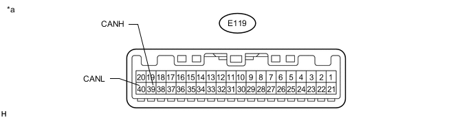
CHECK COMBINATION METER ASSEMBLY
Text in Illustration *a Component without harness connected
(Combination Meter Assembly)
- -
-
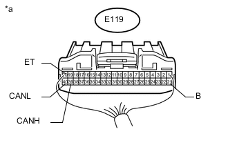
Text in Illustration *a Rear view of wire harness connector
(to Combination Meter Assembly)
Disconnect the combination meter assembly connector.
-
Measure the resistance according to the value(s) in the table below.
Terminal No. (Symbol) Wiring Color Switch Condition Specified Condition E119-39 (CANH) - E119-40 (CANL) BE - W Cable disconnected from negative (-) battery terminal 108 to 132 Ω E119-39 (CANH) - E119-20 (ET) BE - BR Cable disconnected from negative (-) battery terminal 200 Ω or higher E119-40 (CANL) - E119-20 (ET) W - BR Cable disconnected from negative (-) battery terminal 200 Ω or higher E119-39 (CANH) - E119-21 (B) BE - V Cable disconnected from negative (-) battery terminal 6 kΩ or higher E119-40 (CANL) - E119-21 (B) W - V Cable disconnected from negative (-) battery terminal 6 kΩ or higher
-
-
CHECK AIRBAG SENSOR ASSEMBLY
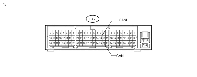
Text in Illustration *a Component without harness connected
(Airbag Sensor Assembly)
- -
-
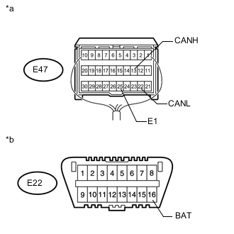
Text in Illustration *a Rear view of wire harness connector
(to Airbag Sensor Assembly)
*b Front view of DLC3 Disconnect the airbag sensor assembly connector.
-
Measure the resistance according to the value(s) in the table below.
Terminal No. (Symbol) Wiring Color Switch Condition Specified Condition E47-13 (CANH) - E47-22 (CANL) GR - W Cable disconnected from negative (-) battery terminal 54 to 69 Ω E47-13 (CANH) - E47-25 (E1) GR - BR Cable disconnected from negative (-) battery terminal 200 Ω or higher E47-22 (CANL) - E47-25 (E1) W - BR Cable disconnected from negative (-) battery terminal 200 Ω or higher E47-13 (CANH) - E22-16 (BAT) GR - L Cable disconnected from negative (-) battery terminal 6 kΩ or higher E47-22 (CANL) - E22-16 (BAT) W - L Cable disconnected from negative (-) battery terminal 6 kΩ or higher
-
-
CHECK MULTI-MEDIA MODULE RECEIVER ASSEMBLY (for Multi-media Module Receiver Type)
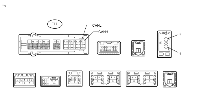
Text in Illustration *a Component without harness connected
(Multi-media Module Receiver Assembly)
- -
-
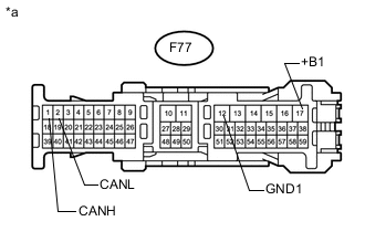
Text in Illustration *a Front view of wire harness connector
(to Multi-media Module Receiver Assembly)
Disconnect the multi-media module receiver assembly connector.
-
Measure the resistance according to the value(s) in the table below.
Terminal No. (Symbol) Wiring Color Switch Condition Specified Condition F77-1 (CANH) - F77-2 (CANL) G - GR Cable disconnected from negative (-) battery terminal 54 to 69 Ω F77-1 (CANH) - F77-12 (GND1) G - W-B Cable disconnected from negative (-) battery terminal 200 Ω or higher F77-2 (CANL) - F77-12 (GND1) GR - W-B Cable disconnected from negative (-) battery terminal 200 Ω or higher F77-1 (CANH) - F77-17 (+B1) G - V Cable disconnected from negative (-) battery terminal 6 kΩ or higher F77-2 (CANL) - F77-17 (+B1) GR - V Cable disconnected from negative (-) battery terminal 6 kΩ or higher
-
-
CHECK RADIO AND DISPLAY RECEIVER ASSEMBLY (for Radio and Display Type)
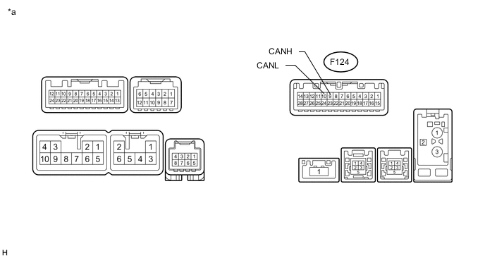
Text in Illustration *a Component without harness connected
(Radio and Display Receiver Assembly)
- -
-
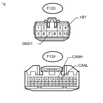
Text in Illustration *a Front view of wire harness connector
(to Radio and Display Receiver Assembly)
Disconnect the radio and display receiver assembly connectors.
-
Measure the resistance according to the value(s) in the table below.
Terminal No. (Symbol) Wiring Color Switch Condition Specified Condition F124-9 (CANH) - F124-10 (CANL) G - GR Cable disconnected from negative (-) battery terminal 54 to 69 Ω F124-9 (CANH) - F120-7 (GND1) G - W-B Cable disconnected from negative (-) battery terminal 200 Ω or higher F124-10 (CANL) - F120-7 (GND1) GR - W-B Cable disconnected from negative (-) battery terminal 200 Ω or higher F124-9 (CANH) - F120-4 (+B1) G - V Cable disconnected from negative (-) battery terminal 6 kΩ or higher F124-10 (CANL) - F120-4 (+B1) GR - V Cable disconnected from negative (-) battery terminal 6 kΩ or higher
-
-
CHECK SPIRAL WITH SENSOR CABLE SUB-ASSEMBLY (STEERING ANGLE SENSOR)
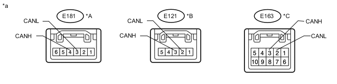
Text in Illustration *A w/o Variable Gear Ratio Steering System, w/o Entry and Start System *B w/o Variable Gear Ratio Steering System, w/ Entry and Start System *C w/ Variable Gear Ratio Steering System - - *a Component without harness connected
(Spiral with Sensor Cable Sub-assembly [Steering Angle Sensor])
- -
-
Disconnect the spiral with sensor cable sub-assembly (steering angle sensor) connector.
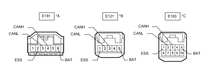
Text in Illustration *A w/o Variable Gear Ratio Steering System, w/o Entry and Start System *B w/o Variable Gear Ratio Steering System, w/ Entry and Start System *C w/ Variable Gear Ratio Steering System - - *a Front view of wire harness connector
(to Spiral with Sensor Cable Sub-assembly [Steering Angle Sensor])
- - -
Measure the resistance according to the value(s) in the table below.
w/o Variable Gear Ratio Steering System, w/o Entry and Start System Terminal No. (Symbol) Wiring Color Switch Condition Specified Condition E181-4 (CANH) - E181-3 (CANL) GR - W Cable disconnected from negative (-) battery terminal 54 to 69 Ω E181-4 (CANH) - E181-2 (ESS) GR - W-B Cable disconnected from negative (-) battery terminal 200 Ω or higher E181-3 (CANL) - E181-2 (ESS) W - W-B Cable disconnected from negative (-) battery terminal 200 Ω or higher E181-4 (CANH) - E181-6 (BAT) GR - R Cable disconnected from negative (-) battery terminal 6 kΩ or higher E181-3 (CANL) - E181-6 (BAT) W - R Cable disconnected from negative (-) battery terminal 6 kΩ or higher w/o Variable Gear Ratio Steering System, w/ Entry and Start System Terminal No. (Symbol) Wiring Color Switch Condition Specified Condition E121-3 (CANH) - E121-2 (CANL) GR - W Cable disconnected from negative (-) battery terminal 54 to 69 Ω E121-3 (CANH) - E121-1 (ESS) GR - W-B Cable disconnected from negative (-) battery terminal 200 Ω or higher E121-2 (CANL) - E121-1 (ESS) W - W-B Cable disconnected from negative (-) battery terminal 200 Ω or higher E121-3 (CANH) - E121-5 (BAT) GR - R Cable disconnected from negative (-) battery terminal 6 kΩ or higher E121-2 (CANL) - E121-5 (BAT) W - R Cable disconnected from negative (-) battery terminal 6 kΩ or higher w/ Variable Gear Ratio Steering System Terminal No. (Symbol) Wiring Color Switch Condition Specified Condition E163-3 (CANH) - E163-2 (CANL) GR - W Cable disconnected from negative (-) battery terminal 54 to 69 Ω E163-3 (CANH) - E163-1 (ESS) GR - W-B Cable disconnected from negative (-) battery terminal 200 Ω or higher E163-2 (CANL) - E163-1 (ESS) W - W-B Cable disconnected from negative (-) battery terminal 200 Ω or higher E163-3 (CANH) - E163-5 (BAT) GR - R Cable disconnected from negative (-) battery terminal 6 kΩ or higher E163-2 (CANL) - E163-5 (BAT) W - R Cable disconnected from negative (-) battery terminal 6 kΩ or higher
-
-
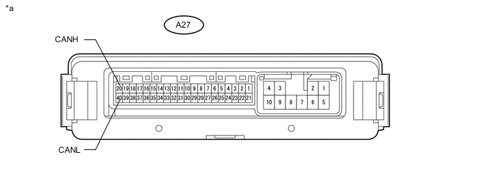
CHECK 4WD CONTROL ECU
Text in Illustration *a Component without harness connected
(4WD Control ECU)
- -
-
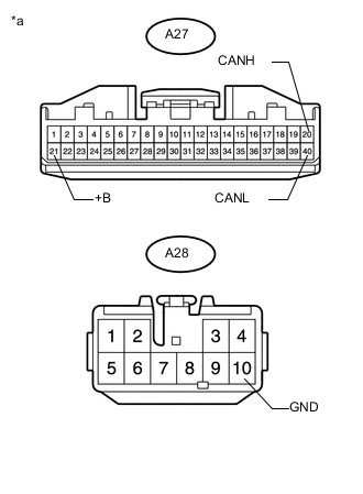
Text in Illustration *a Front view of wire harness connector
(to 4WD Control ECU)
Disconnect the 4WD control ECU connectors.
-
Measure the resistance according to the value(s) in the table below.
Terminal No. (Symbol) Wiring Color Switch Condition Specified Condition A27-20 (CANH) - A27-40 (CANL) P - W Cable disconnected from negative (-) battery terminal 54 to 69 Ω A27-20 (CANH) - A28-10 (GND) P - W-B Cable disconnected from negative (-) battery terminal 200 Ω or higher A27-40 (CANL) - A28-10 (GND) W - W-B Cable disconnected from negative (-) battery terminal 200 Ω or higher A27-20 (CANH) - A27-21 (+B) P - R Cable disconnected from negative (-) battery terminal 6 kΩ or higher A27-40 (CANL) - A27-21 (+B) W - R Cable disconnected from negative (-) battery terminal 6 kΩ or higher
-
-
CHECK TIRE PRESSURE WARNING ECU (w/ Tire Pressure Warning System)
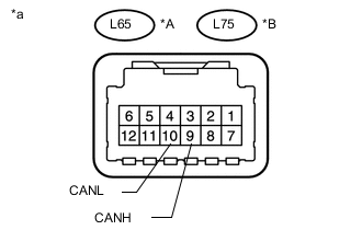
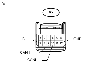
Text in Illustration *A w/o Front Antenna *B w/ Front Antenna *a Component without harness connected
(Tire Pressure Warning ECU)
-
Text in Illustration *a Front view of wire harness connector
(to Tire Pressure Warning ECU)
w/o Front Antenna:
-
Disconnect the tire pressure warning ECU connector.
-
Measure the resistance according to the value(s) in the table below.
Terminal No. (Symbol) Wiring Color Switch Condition Specified Condition L65-9 (CANH) - L65-10 (CANL) R - W Cable disconnected from negative (-) battery terminal 54 to 69 Ω L65-9 (CANH) - L65-12 (GND) R - BR Cable disconnected from negative (-) battery terminal 200 Ω or higher L65-10 (CANL) - L65-12 (GND) W - BR Cable disconnected from negative (-) battery terminal 200 Ω or higher L65-9 (CANH) - L65-7 (+B) R - R Cable disconnected from negative (-) battery terminal 6 kΩ or higher L65-10 (CANL) - L65-7 (+B) W - R Cable disconnected from negative (-) battery terminal 6 kΩ or higher
-
-
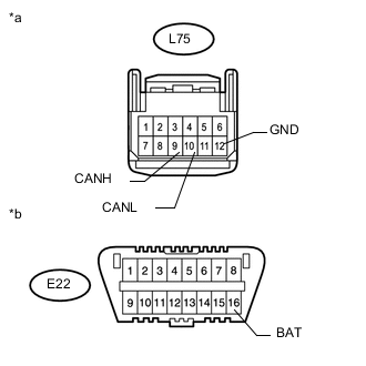
Text in Illustration *a Front view of wire harness connector
(to Tire Pressure Warning ECU)
*b Front view DLC3 w/ Front Antenna:
-
Disconnect the tire pressure warning ECU connector.
-
Measure the resistance according to the value(s) in the table below.
Terminal No. (Symbol) Wiring Color Switch Condition Specified Condition L75-9 (CANH) - L75-10 (CANL) R - W Cable disconnected from negative (-) battery terminal 54 to 69 Ω L75-9 (CANH) - L75-12 (GND) R - BR Cable disconnected from negative (-) battery terminal 200 Ω or higher L75-10 (CANL) - L75-12 (GND) W - BR Cable disconnected from negative (-) battery terminal 200 Ω or higher L75-9 (CANH) - E22-16 (BAT) R - L Cable disconnected from negative (-) battery terminal 6 kΩ or higher L75-10 (CANL) - E22-16 (BAT) W - L Cable disconnected from negative (-) battery terminal 6 kΩ or higher
-
-
-
CHECK STEERING CONTROL ECU (w/ Variable Gear Ratio Steering System)
Text in Illustration *a Component without harness connected
(Steering Control ECU)
- -
-
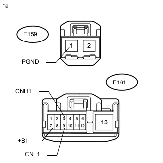
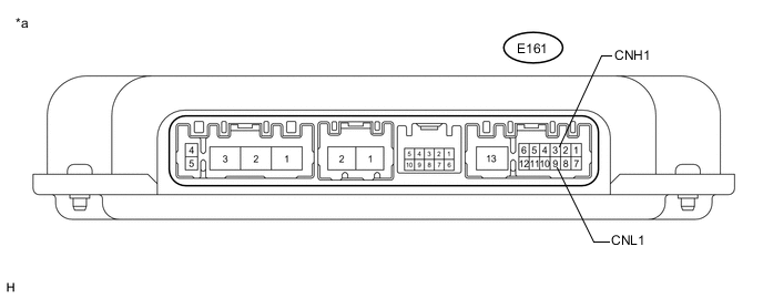
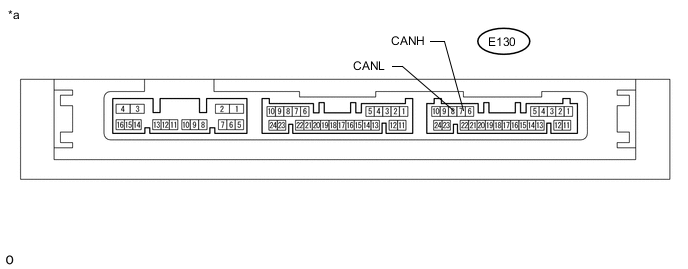
Text in Illustration *a Front view of wire harness connector
(to Steering Control ECU)
Disconnect the steering control ECU connectors.
-
Measure the resistance according to the value(s) in the table below.
Terminal No. (Symbol) Wiring Color Switch Condition Specified Condition E161-3 (CNH1) - E161-9 (CNL1) R - W Cable disconnected from negative (-) battery terminal 54 to 69 Ω E161-3 (CNH1) - E159-1 (PGND) R - W-B Cable disconnected from negative (-) battery terminal 200 Ω or higher E161-9 (CNL1) - E159-1 (PGND) W - W-B Cable disconnected from negative (-) battery terminal 200 Ω or higher E161-3 (CNH1) - E161-7 (+BI) R - R Cable disconnected from negative (-) battery terminal 6 kΩ or higher E161-9 (CNL1) - E161-7 (+BI) W - R Cable disconnected from negative (-) battery terminal 6 kΩ or higher
-
-
CHECK POWER STEERING ECU ASSEMBLY (w/ Variable Flow Control Solenoid Valve)
Text in Illustration *a Component without harness connected
(Power Steering ECU Assembly)
-
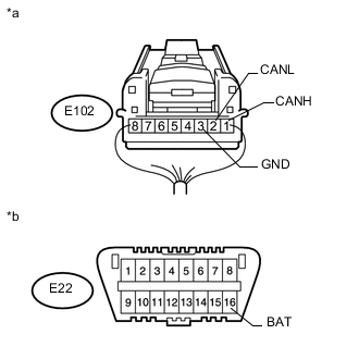
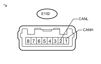
Text in Illustration *a Front view of wire harness connector
(to Power Steering ECU Assembly)
*b Front view of DLC3 Disconnect the power steering ECU assembly connector.
-
Measure the resistance according to the value(s) in the table below.
Terminal No. (Symbol) Wiring Color Switch Condition Specified Condition E102-1 (CANH) - E102-2 (CANL) LG - W Cable disconnected from negative (-) battery terminal 54 to 69 Ω E102-1 (CANH) - E102-3 (GND) LG - W-B Cable disconnected from negative (-) battery terminal 200 Ω or higher E102-2 (CANL) - E102-3 (GND) W - W-B Cable disconnected from negative (-) battery terminal 200 Ω or higher E102-1 (CANH) - E22-16 (BAT) LG - L Cable disconnected from negative (-) battery terminal 6 kΩ or higher E102-2 (CANL) - E22-16 (BAT) W - L Cable disconnected from negative (-) battery terminal 6 kΩ or higher
-
-
CHECK CERTIFICATION ECU (SMART KEY ECU ASSEMBLY) (w/ Entry and Start System)
Text in Illustration *a Component without harness connected
(Certification ECU [Smart Key ECU Assembly])
- -
-
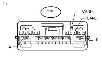
Text in Illustration *a Front view of wire harness connector
(to Certification ECU [Smart Key ECU Assembly])
Disconnect the certification ECU (smart key ECU assembly) connector.
-
Measure the resistance according to the value(s) in the table below.
Terminal No. (Symbol) Wiring Color Switch Condition Specified Condition E130-7 (CANH) - E130-8 (CANL) B - W Cable disconnected from negative (-) battery terminal 54 to 69 Ω E130-7 (CANH) - E130-11 (E) B - BR Cable disconnected from negative (-) battery terminal 200 Ω or higher E130-8 (CANL) - E130-11 (E) W - BR Cable disconnected from negative (-) battery terminal 200 Ω or higher E130-7 (CANH) - E130-10 (+B) B - P Cable disconnected from negative (-) battery terminal 6 kΩ or higher E130-8 (CANL) - E130-10 (+B) W - P Cable disconnected from negative (-) battery terminal 6 kΩ or higher
-
-
CHECK HEADLIGHT LEVELING ECU ASSEMBLY (w/ Automatic High Beam System)
Text in Illustration *a Component without harness connected
(Headlight Leveling ECU Assembly)
- -
-
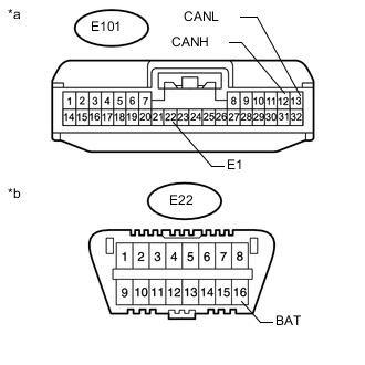
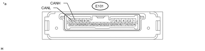
Text in Illustration *a Front view of wire harness connector
(to Headlight Leveling ECU Assembly)
*b Front view of DLC3 Disconnect the headlight leveling ECU assembly connector.
-
Measure the resistance according to the value(s) in the table below.
Terminal No. (Symbol) Wiring Color Switch Condition Specified Condition E101-12 (CANH) - E101-13 (CANL) LG - B Cable disconnected from negative (-) battery terminal 54 to 69 Ω E101-12 (CANH) - E101-22 (E1) LG - W-B Cable disconnected from negative (-) battery terminal 200 Ω or higher E101-13 (CANL) - E101-22 (E1) B - W-B Cable disconnected from negative (-) battery terminal 200 Ω or higher E101-12 (CANH) - E22-16 (BAT) LG - L Cable disconnected from negative (-) battery terminal 6 kΩ or higher E101-13 (CANL) - E22-16 (BAT) B - L Cable disconnected from negative (-) battery terminal 6 kΩ or higher
-
-
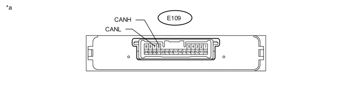
CHECK HEADLIGHT LEVELING ECU ASSEMBLY (w/o Automatic High Beam System)
Text in Illustration *a Component without harness connected
(Headlight Leveling ECU Assembly)
- -
-
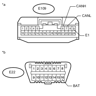
Text in Illustration *a Front view of wire harness connector
(to Headlight Leveling ECU Assembly)
*b Front view of DLC3 Disconnect the headlight leveling ECU assembly connector.
-
Measure the resistance according to the value(s) in the table below.
Terminal No. (Symbol) Wiring Color Switch Condition Specified Condition E109-6 (CANH) - E109-7 (CANL) LG - B Cable disconnected from negative (-) battery terminal 54 to 69 Ω E109-6 (CANH) - E109-9 (E1) LG - W-B Cable disconnected from negative (-) battery terminal 200 Ω or higher E109-7 (CANL) - E109-9 (E1) B - W-B Cable disconnected from negative (-) battery terminal 200 Ω or higher E109-6 (CANH) - E22-16 (BAT) LG - L Cable disconnected from negative (-) battery terminal 6 kΩ or higher E109-7 (CANL) - E22-16 (BAT) B - L Cable disconnected from negative (-) battery terminal 6 kΩ or higher
-
-
CHECK OUTER MIRROR CONTROL ECU ASSEMBLY LH (w/ Memory)

Text in Illustration *a Component without harness connected
(Outer Mirror Control ECU Assembly LH)
- -
-
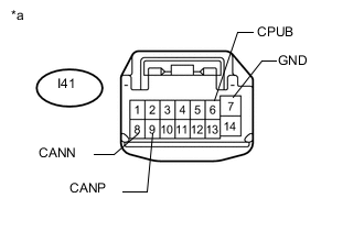
Text in Illustration *a Front view of wire harness connector
(to Outer Mirror Control ECU Assembly LH)
Disconnect the outer mirror control ECU assembly LH connector.
-
Measure the resistance according to the value(s) in the table below.
Terminal No. (Symbol) Wiring Color Switch Condition Specified Condition I41-9 (CANP) - I41-8 (CANN) BE - L Cable disconnected from negative (-) battery terminal 54 to 69 Ω I41-9 (CANP) - I41-7 (GND) BE - W-B Cable disconnected from negative (-) battery terminal 200 Ω or higher I41-8 (CANN) - I41-7 (GND) L - W-B Cable disconnected from negative (-) battery terminal 200 Ω or higher I41-9 (CANP) - I41-6 (CPUB) BE - G Cable disconnected from negative (-) battery terminal 6 kΩ or higher I41-8 (CANN) - I41-6 (CPUB) L - G Cable disconnected from negative (-) battery terminal 6 kΩ or higher
-
-
CHECK OUTER MIRROR CONTROL ECU ASSEMBLY RH (w/ Memory)

Text in Illustration *a Component without harness connected
(Outer Mirror Control ECU Assembly RH)
- -
-

Text in Illustration *a Front view of wire harness connector
(to Outer Mirror Control ECU Assembly RH)
Disconnect the outer mirror control ECU assembly RH connector.
-
Measure the resistance according to the value(s) in the table below.
Terminal No. (Symbol) Wiring Color Switch Condition Specified Condition I38-9 (CANP) - I38-8 (CANN) LG - L Cable disconnected from negative (-) battery terminal 54 to 69 Ω I38-9 (CANP) - I38-7 (GND) LG - W-B Cable disconnected from negative (-) battery terminal 200 Ω or higher I38-8 (CANN) - I38-7 (GND) L - W-B Cable disconnected from negative (-) battery terminal 200 Ω or higher I38-9 (CANP) - I38-6 (CPUB) LG - G Cable disconnected from negative (-) battery terminal 6 kΩ or higher I38-8 (CANN) - I38-6 (CPUB) L - G Cable disconnected from negative (-) battery terminal 6 kΩ or higher
-
-
CHECK MULTIPLEX TILT AND TELESCOPIC ECU (w/ Power Tilt and Power Telescopic Steering Column System)

Text in Illustration *a Component without harness connected
(Multiplex Tilt and Telescopic ECU)
- -
-
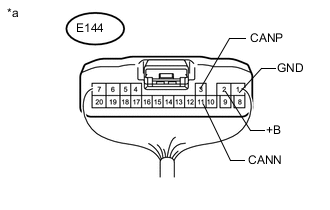
Text in Illustration *a Rear view of wire harness connector
(to Multiplex Tilt and Telescopic ECU)
Disconnect the multiplex tilt and telescopic ECU connector.
-
Measure the resistance according to the value(s) in the table below.
Terminal No. (Symbol) Wiring Color Switch Condition Specified Condition E144-3 (CANP) - E144-11 (CANN) P - L Cable disconnected from negative (-) battery terminal 54 to 69 Ω E144-3 (CANP) - E144-1 (GND) P - W-B Cable disconnected from negative (-) battery terminal 200 Ω or higher E144-11 (CANN) - E144-1 (GND) L - W-B Cable disconnected from negative (-) battery terminal 200 Ω or higher E144-3 (CANP) - E144-2 (+B) P - LA-W Cable disconnected from negative (-) battery terminal 6 kΩ or higher E144-11 (CANN) - E144-2 (+B) L - LA-W Cable disconnected from negative (-) battery terminal 6 kΩ or higher
-
-
CHECK POWER SEAT SWITCH ASSEMBLY (w/ Memory)

Text in Illustration *a Component without harness connected
(Power Seat Switch Assembly)
- -
-
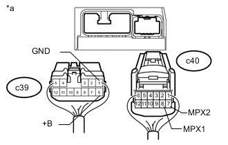
Text in Illustration *a Rear view of wire harness connector
(to Power Seat Switch Assembly)
Disconnect the power seat switch assembly connectors.
-
Measure the resistance according to the value(s) in the table below.
Terminal No. (Symbol) Wiring Color Switch Condition Specified Condition c40-8 (MPX1) - c40-7 (MPX2) V - L Cable disconnected from negative (-) battery terminal 54 to 69 Ω c40-8 (MPX1) - c39-1 (GND) V - W-B Cable disconnected from negative (-) battery terminal 200 Ω or higher c40-7 (MPX2) - c39-1 (GND) L - W-B Cable disconnected from negative (-) battery terminal 200 Ω or higher c40-8 (MPX1) - c39-6 (+B) V - L Cable disconnected from negative (-) battery terminal 6 kΩ or higher c40-7 (MPX2) - c39-6 (+B) L - L Cable disconnected from negative (-) battery terminal 6 kΩ or higher
-
-
CHECK POWER BACK DOOR UNIT ASSEMBLY (POWER BACK DOOR ECU) (w/ Power Back Door System)
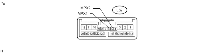
Text in Illustration *a Component without harness connected
(Power Back Door Unit Assembly [Power Back Door ECU])
- -
-
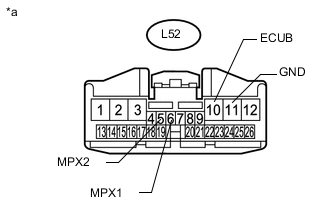
Text in Illustration *a Front view of wire harness connector
(to Power Back Door Unit Assembly [Power Back Door ECU])
Disconnect the power back door unit assembly (power back door ECU) connector.
-
Measure the resistance according to the value(s) in the table below.
Terminal No. (Symbol) Wiring Color Switch Condition Specified Condition L52-6 (MPX1) - L52-5 (MPX2) V - L Cable disconnected from negative (-) battery terminal 54 to 69 Ω L52-6 (MPX1) - L52-11 (GND) V - W-B Cable disconnected from negative (-) battery terminal 200 Ω or higher L52-5 (MPX2) - L52-11 (GND) L - W-B Cable disconnected from negative (-) battery terminal 200 Ω or higher L52-6 (MPX1) - L52-10 (ECUB) V - R Cable disconnected from negative (-) battery terminal 6 kΩ or higher L52-5 (MPX2) - L52-10 (ECUB) L - R Cable disconnected from negative (-) battery terminal 6 kΩ or higher
-
-
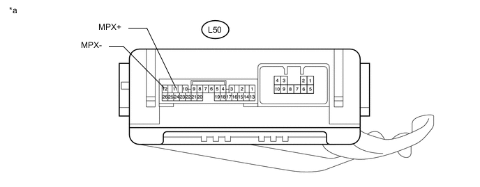
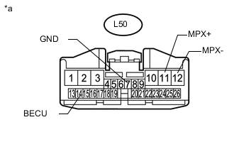
CHECK NO. 2 MAIN BODY ECU (w/ Tail Gate Closer System)
Text in Illustration *a Component without harness connected
(No. 2 Main Body ECU)
- -
-
Text in Illustration *a Front view of wire harness connector
(to No. 2 Main Body ECU)
Disconnect the No. 2 main body ECU connector.
-
Measure the resistance according to the value(s) in the table below.
Terminal No. (Symbol) Wiring Color Switch Condition Specified Condition L50-11 (MPX+) - L50-12 (MPX-) LG - L Cable disconnected from negative (-) battery terminal 54 to 69 Ω L50-11 (MPX+) - L50-7 (GND) LG - W-B Cable disconnected from negative (-) battery terminal 200 Ω or higher L50-12 (MPX-) - L50-7 (GND) L - W-B Cable disconnected from negative (-) battery terminal 200 Ω or higher L50-11 (MPX+) - L50-14 (BECU) LG - R Cable disconnected from negative (-) battery terminal 6 kΩ or higher L50-12 (MPX-) - L50-14 (BECU) L - R Cable disconnected from negative (-) battery terminal 6 kΩ or higher
-
-
CHECK BUS BUFFER ECU (w/ Bus Buffer ECU)
-
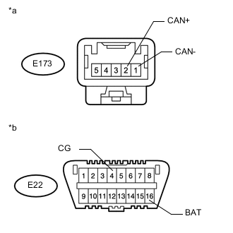
Text in Illustration *a Front view of wire harness connector
(to Bus Buffer ECU)
*b Front view of DLC3 Disconnect the bus buffer ECU connector.
-
Measure the resistance according to the value(s) in the table below.
Terminal No. (Symbol) Wiring Color Switch Condition Specified Condition E173-2 (CAN+) - E173-1 (CAN-) BE - GR Cable disconnected from negative (-) battery terminal 54 to 69 Ω E173-2 (CAN+) - E22-4 (CG) BE - W-B Cable disconnected from negative (-) battery terminal 200 Ω or higher E173-1 (CAN-) - E22-4 (CG) GR - W-B Cable disconnected from negative (-) battery terminal 200 Ω or higher E173-2 (CAN+) - E22-16 (BAT) BE - L Cable disconnected from negative (-) battery terminal 6 kΩ or higher E173-1 (CAN-) - E22-16 (BAT) GR - L Cable disconnected from negative (-) battery terminal 6 kΩ or higher
-