CAN COMMUNICATION SYSTEM(for LHD without Central Gateway ECU) SYSTEM DIAGRAM
-
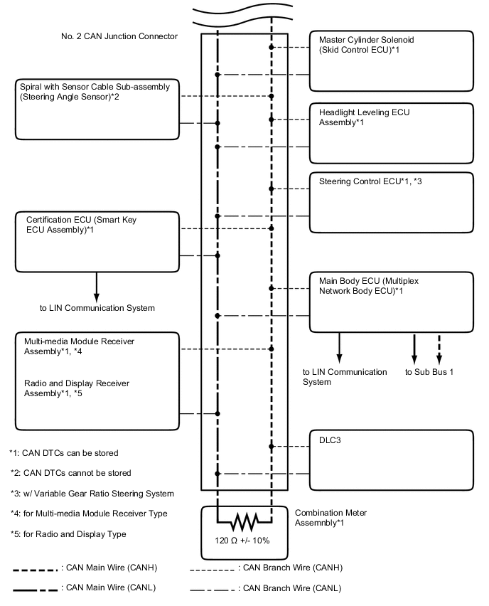
SYSTEM DIAGRAM
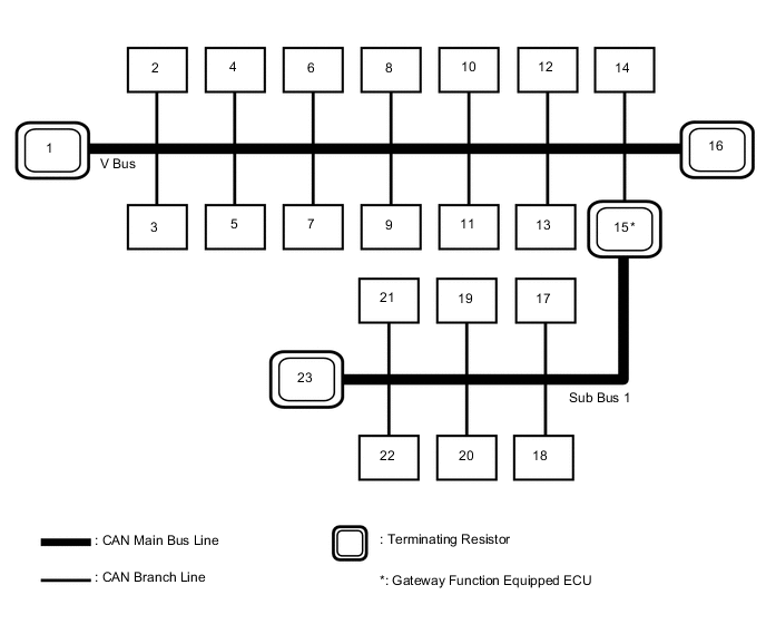
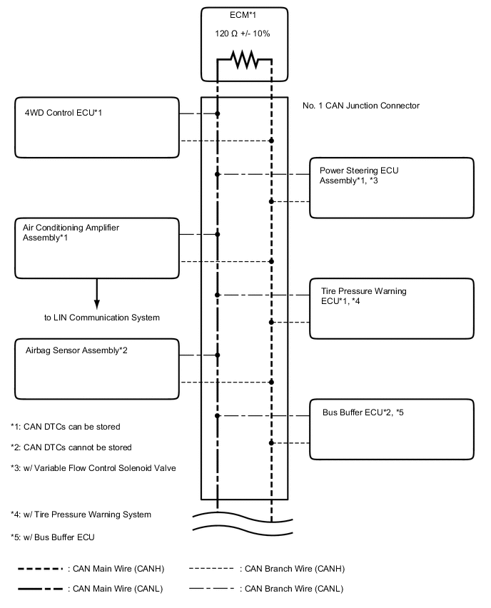
No. ECU/Sensor name 1 ECM 2 DLC3 3 4WD Control ECU 4 Tire Pressure Warning ECU*1 5 Airbag Sensor Assembly 6 Air Conditioning Amplifier Assembly 7 Headlight Leveling ECU Assembly 8 Master Cylinder Solenoid (Skid Control ECU) 9 Steering Control ECU*2 10 Certification ECU (Smart Key ECU Assembly)*3 11 Power Steering ECU Assembly*4 12 Spiral with Sensor Cable Sub-assembly (Steering Angle Sensor) 13
-
Multi-media Module Receiver Assembly*9
-
Radio and Display Receiver Assembly*10
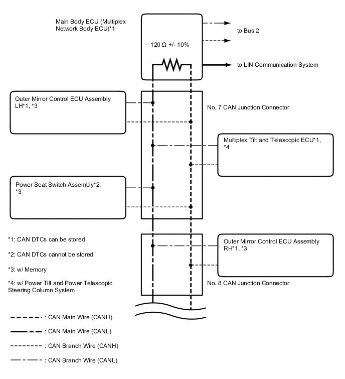
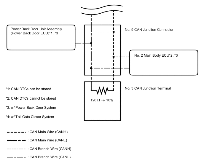
14 Bus Buffer ECU*11 15 Main Body ECU (Multiplex Network Body ECU) 16 Combination Meter Assembly 17 Outer Mirror Control ECU Assembly RH*5 18 Outer Mirror Control ECU Assembly LH*5 19 Power Seat Switch Assembly*5 20 Multiplex Tilt and Telescopic ECU*6 21 Power Back Door Unit Assembly (Power Back Door ECU)*7 22 No. 2 Main Body ECU*8 23 No. 3 CAN Junction Terminal
-
*1: w/ Tire Pressure Warning System
-
*2: w/ Variable Gear Ratio Steering System
-
*3: w/ Entry and Start System
-
*4: w/ Variable Flow Control Solenoid Valve
-
*5: w/ Memory
-
*6: w/ Power Tilt and Power Telescopic Steering Column System
-
*7: w/ Power Back Door System
-
*8: w/ Tail Gate Closer System
-
*9: for Multi-media Module Receiver Type
-
*10: for Radio and Display Type
-
*11: w/ Bus Buffer ECU
-
-
V BUS
-
SUB BUS 1