CAN COMMUNICATION SYSTEM(for LHD without Central Gateway ECU) Air Conditioning Amplifier Communication Stop Mode
DESCRIPTION
| Detection Item | Symptom | Trouble Area |
|---|---|---|
| Air Conditioning Amplifier Communication Stop Mode | Either Condition is met:
|
|
WIRING DIAGRAM
CAUTION / NOTICE / HINT
Note
-
Before measuring the resistance of the CAN bus, turn the ignition switch off and leave the vehicle for 1 minute or more without operating the key, switches or opening or closing the doors. After that, disconnect the cable from the negative (-) battery terminal and leave the vehicle for 1 minute or more before measuring the resistance.
-
After turning the ignition switch off, waiting time may be required before disconnecting the cable from the battery terminal. Therefore, make sure to read the disconnecting the cable from the battery terminal notice before proceeding with work Click here.
-
Inspect the fuses for circuits related to this system before performing the following inspection procedure.
Tech Tips
-
Operating the ignition switch, any switches or any doors triggers related ECU and sensor communication with the CAN, which causes resistance variation.
-
Even after DTCs are cleared, if a DTC is stored again after driving the vehicle for a while, the malfunction may be occurring due to vibration of the vehicle. In such a case, wiggling the ECUs or wire harness while performing the inspection below may help determine the cause of the malfunction.
PROCEDURE
-
CHECK FOR OPEN IN CAN BUS WIRE (AIR CONDITIONING AMPLIFIER ASSEMBLY CAN BRANCH WIRE)
-
Disconnect the cable from the negative (-) battery terminal.
-
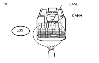
Text in Illustration *a Rear view of wire harness connector
(to Air Conditioning Amplifier Assembly)
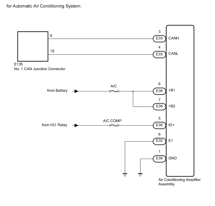
for Automatic Air Conditioning System:
-
Disconnect the air conditioning amplifier assembly connector.
-
Measure the resistance according to the value(s) in the table below.
Standard Resistance Tester Connection Condition Specified Condition E35-3 (CANH) - E35-4 (CANL) Cable disconnected from negative (-) battery terminal 54 to 69 Ω
-
-
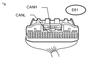
Text in Illustration *a Rear view of wire harness connector
(to Air Conditioning Amplifier Assembly)
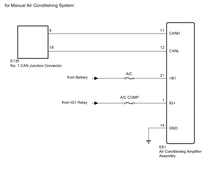
for Manual Air Conditioning System:
-
Disconnect the air conditioning amplifier assembly connector.
-
Measure the resistance according to the value(s) in the table below.
Standard Resistance Tester Connection Condition Specified Condition E81-11 (CANH) - E81-12 (CANL) Cable disconnected from negative (-) battery terminal 54 to 69 Ω
-
NG 
REPAIR OR REPLACE CAN BRANCH WIRE CONNECTED TO AIR CONDITIONING AMPLIFIER ASSEMBLY (CANH, CANL)
OK 
-
-
CHECK HARNESS AND CONNECTOR (AIR CONDITIONING AMPLIFIER ASSEMBLY - BATTERY AND BODY GROUND)
-
Connect the cable to the negative (-) battery terminal.
Note
When connecting the cable, some systems need to be initialized after the cable is reconnected Click here.
-
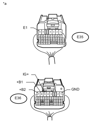
Text in Illustration *a Rear view of wire harness connector
(to Air Conditioning Amplifier Assembly)
for Automatic Air Conditioning System:
-
Disconnect the air conditioning amplifier assembly connector.
-
Measure the voltage according to the value(s) in the table below.
Standard Voltage Tester Connection Condition Specified Condition E36-6 (+B1) - Body ground Always 11 to 14 V E36-7 (+B2) - Body ground Always 11 to 14 V E36-5 (IG+) - Body ground Ignition switch ON 11 to 14 V -
Measure the resistance according to the value(s) in the table below.
Standard Resistance Tester Connection Condition Specified Condition E35-6 (E1) - Body ground Always Below 1 Ω E36-1 (GND) - Body ground Always Below 1 Ω
-
-
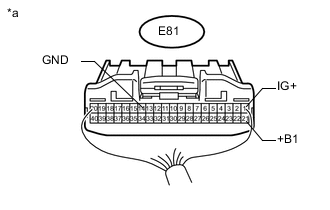
Text in Illustration *a Rear view of wire harness connector
(to Air Conditioning Amplifier Assembly)
for Manual Air Conditioning System:
-
Measure the voltage according to the value(s) in the table below.
Standard Voltage Tester Connection Condition Specified Condition E81-21 (+B1) - Body ground Always 11 to 14 V E81-1 (IG+) - Body ground Ignition switch ON 11 to 14 V -
Measure the resistance according to the value(s) in the table below.
Standard Resistance Tester Connection Condition Specified Condition E81-14 (GND) - Body ground Always Below 1 Ω
-
OK
REPLACE AIR CONDITIONING AMPLIFIER ASSEMBLY Click here
NG
REPAIR OR REPLACE HARNESS OR CONNECTOR
-