ENGINE ASSEMBLY REMOVAL
CAUTION / NOTICE / HINT
Note
w/ DPF:
When fuel lines are disconnected, air may enter the fuel lines, leading to engine starting trouble. Therefore, perform forced regeneration and bleed the air from the fuel lines.
PROCEDURE
-
RECOVER REFRIGERANT FROM REFRIGERATION SYSTEM
-
PRECAUTION
Note
After turning the ignition switch off, waiting time may be required before disconnecting the cable from the battery terminal. Therefore, make sure to read the disconnecting the cable from the battery terminal notice before proceeding with work Click here.
-
DISCONNECT CABLE FROM NEGATIVE BATTERY TERMINAL
Note
When disconnecting the cable some systems need to be initialized after the cable is reconnected Click here.
-
REMOVE COWL TOP VENTILATOR LOUVER SUB-ASSEMBLY
-
REMOVE NO. 1 ENGINE COVER SUB-ASSEMBLY (w/ Intercooler)
-
REMOVE UPPER RADIATOR SUPPORT SEAL
-
REMOVE MAIN BATTERY
-
REMOVE SUB-BATTERY
-
REMOVE FRONT WHEEL
-
REMOVE HOOD SUB-ASSEMBLY
-
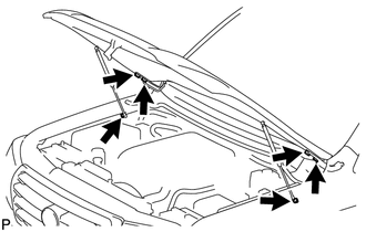
Remove the 2 hood stay bolts. Then disconnect the 2 hood supports.
Note
-
Avoid touching the stroke portions of the rod as much as possible to prevent foreign matter from attaching to it. Be sure to hold the cylinders while servicing.
-
Do not wear cotton gloves or other similar materials when handling the rod. Fibers may attach to the rod and result in gas leaks.
-
Do not apply any load to the cylinders in the horizontal direction in order to prevent the rod from being deformed.
-
Remove the hood support while supporting the hood by hand.
-
-
Remove the 4 bolts and hood.
-
-
REMOVE FRONT FENDER SPLASH SHIELD SUB-ASSEMBLY LH
-
Remove the 3 bolts and screw.
-
Loosen the clip and remove the front fender splash shield LH.
-
-
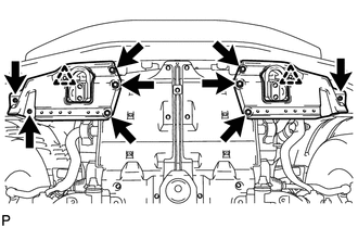
REMOVE FRONT FENDER SPLASH SHIELD SUB-ASSEMBLY RH
-
Remove the 3 bolts and 2 screws.
-
Loosen the clip and remove the front fender splash shield RH.
-
-
REMOVE NO. 1 ENGINE UNDER COVER SUB-ASSEMBLY
-
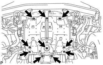
Remove the 10 bolts and No. 1 engine under cover.
-
-
REMOVE NO. 2 ENGINE UNDER COVER
-
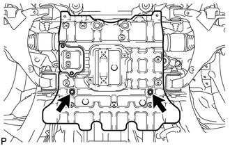
Remove the 2 bolts and No. 2 engine under cover.
-
-
REMOVE OIL PAN PROTECTOR ASSEMBLY (for 1-piece Type)
-
REMOVE OIL PAN PROTECTOR ASSEMBLY LH (for 2-piece Type)
-
REMOVE OIL PAN PROTECTOR ASSEMBLY RH (for 2-piece Type)
-
DRAIN ENGINE COOLANT
-
DRAIN ENGINE OIL
-
Remove the oil filler cap.
-
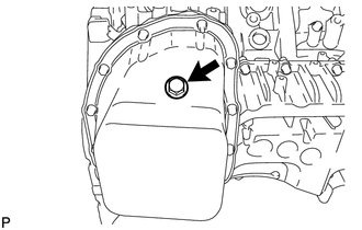
Remove the oil pan drain plug and gasket, and then drain the engine oil into a container.
-
Install a new gasket and the oil pan drain plug.
- Torque:
- 38 N*m { 387 kgf*cm, 28 ft.*lbf }
-
-
REMOVE INTERCOOLER ASSEMBLY (w/ Intercooler)
-
REMOVE NO. 3 ENGINE ROOM WIRE
-
REMOVE AIR CLEANER CAP SUB-ASSEMBLY
-
REMOVE AIR CLEANER FILTER ELEMENT
-
REMOVE AIR CLEANER CASE
-
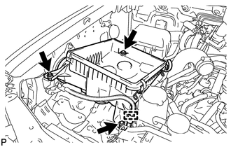
Using a clip remover, detach the wire harness clamp.
-
Remove the 3 bolts and air cleaner case.
-
-
REMOVE NO. 1 AIR CLEANER HOSE
-
REMOVE INTAKE AIR CONNECTOR
-
REMOVE VANE PUMP OIL RESERVOIR ASSEMBLY
-
REMOVE NO. 1 OIL RESERVOIR BRACKET
-
REMOVE RADIATOR RESERVOIR ASSEMBLY
-
REMOVE VANE PUMP ASSEMBLY
-
DISCONNECT NO. 1 RADIATOR HOSE
-
DISCONNECT NO. 2 RADIATOR HOSE
-
REMOVE V-RIBBED BELT (w/ Viscous Heater)
-
REMOVE NO. 1 IDLER PULLEY (w/ Viscous Heater)
-
REMOVE NO. 3 IDLER PULLEY (w/ Viscous Heater)
-
REMOVE V-RIBBED BELT
-
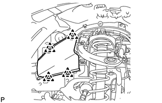
REMOVE FRONT FENDER APRON SEAL FRONT RH
-
Remove the 3 clips and front fender apron seal front RH.
-
-
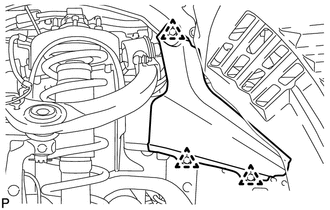
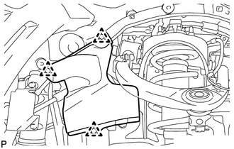
REMOVE FRONT FENDER APRON SEAL REAR RH
-
Remove the 4 clips and front fender apron seal rear RH.
-
-
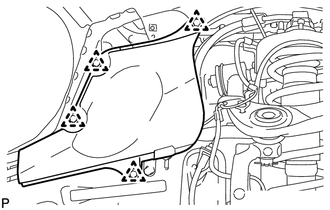
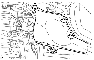
REMOVE FRONT FENDER APRON SEAL FRONT LH
-
w/o KDSS:
Remove the 4 clips and front fender apron seal front LH.
-
w/ KDSS:
Remove the 3 clips and front fender apron seal front LH.
-
-
REMOVE FRONT FENDER APRON SEAL REAR LH
-
Remove the 4 clips and front fender apron seal rear LH.
-
-
REMOVE OIL COOLER TUBE (for Automatic Transmission)
-
REMOVE FAN SHROUD WITH FAN
-
REMOVE FAN PULLEY
-
REMOVE FRONT BUMPER WINCH COVER (w/ Winch)
-
REMOVE RADIATOR GRILLE
-
REMOVE FRONT BUMPER COVER
-
REMOVE TRANSMISSION OIL COOLER AIR DUCT (for Automatic Transmission)
-
DISCONNECT RADIATOR SIDE DEFLECTOR RH (for Manual Transmission)
-
DISCONNECT RADIATOR SIDE DEFLECTOR LH
-
REMOVE RADIATOR ASSEMBLY
-
DISCONNECT FRONT DIFFERENTIAL BREATHER TUBE
-
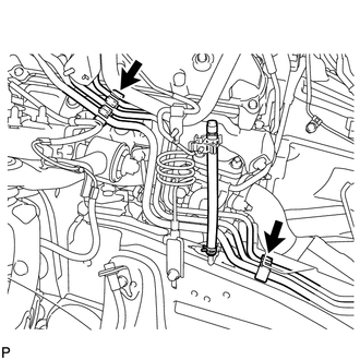
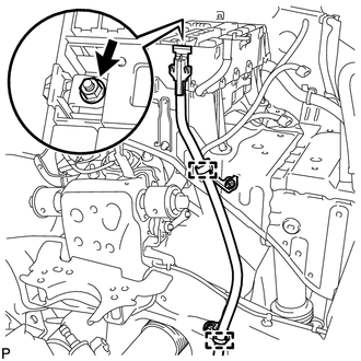
DISCONNECT FUEL TUBE
-
w/ DPF:
Disconnect the 2 fuel tubes from the No. 1 and No. 3 fuel tube clamps.
-
w/o DPF:
Disconnect the 3 fuel tubes from the No. 1 and No. 3 fuel tube clamps.
-
-
REMOVE NO. 1 COOL AIR INLET (w/o Intercooler)
-
REMOVE NO. 2 COOL AIR INLET (w/o Intercooler)
-
DISCONNECT WATER HOSE SUB-ASSEMBLY
-
REMOVE NO. 2 ENGINE OIL LEVEL DIPSTICK GUIDE
-
REMOVE AIR TUBE SUB-ASSEMBLY RH
-
REMOVE DIESEL THROTTLE BODY ASSEMBLY RH
-
DRAIN CLUTCH FLUID (for Manual Transmission)
-
REMOVE CLUTCH HOSE (for Manual Transmission)
-
REMOVE AIR TUBE SUB-ASSEMBLY LH
-
REMOVE TUBE CONNECTOR TO FLEXIBLE HOSE TUBE (for Manual Transmission)
-
REMOVE NO. 1 GAS FILTER
-
REMOVE NO. 3 INTERCOOLER SUPPORT BRACKET
-
REMOVE DIESEL THROTTLE BODY ASSEMBLY LH
-
REMOVE NO. 1 AIR HOSE
-
REMOVE NO. 3 AIR TUBE
-
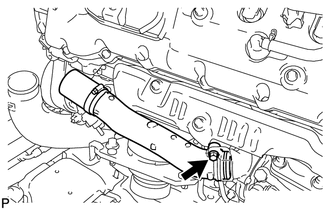
REMOVE NO. 1 AIR TUBE ASSEMBLY
-
Remove the bolt and No. 1 air tube.
-
Remove the O-ring.
-
-
REMOVE NO. 2 AIR HOSE
-
REMOVE NO. 4 AIR TUBE
-
REMOVE NO. 2 AIR TUBE ASSEMBLY
-
Remove the bolt and No. 2 air tube.
-
Remove the O-ring.
-
-
REMOVE NO. 2 AIR CLEANER PIPE SUB-ASSEMBLY
-
REMOVE NO. 1 COOLER REFRIGERANT DISCHARGE HOSE
-
REMOVE SUCTION HOSE SUB-ASSEMBLY
-
REMOVE COOLER COMPRESSOR ASSEMBLY
-
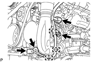
Disconnect the 4 connectors.
-
Using a clip remover, detach the 3 wire harness clamps.
-
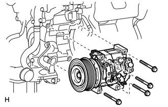
Remove the 4 bolts and cooler compressor.
-
-
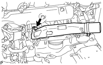
REMOVE NO. 2 INTAKE AIR CONNECTOR PIPE
-
w/ Intercooler:
Disconnect the vacuum hose.
-
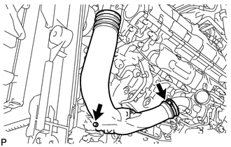
Loosen the hose clamp, and remove the bolt and No. 2 intake air connector pipe.
-
-
REMOVE HEATER WATER PIPE SUB-ASSEMBLY (w/ Viscous Heater)
-
REMOVE NO. 1 AIR CLEANER PIPE SUB-ASSEMBLY
-
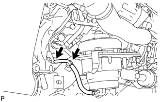
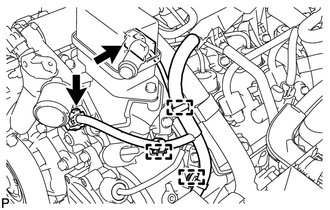
DISCONNECT FUEL HOSE
-
REMOVE NO. 3 WATER BY-PASS PIPE (w/o Viscous Heater)
-
REMOVE NO. 4 WATER BY-PASS PIPE
-
DISCONNECT ENGINE WIRE
-
LH Side:
-
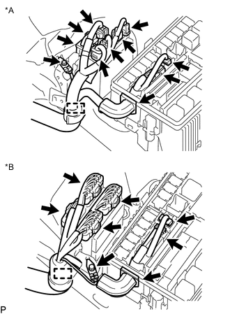
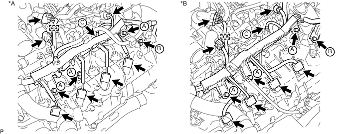
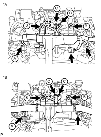
Text in Illustration *A w/ DPF *B w/o DPF w/ DPF:
Disconnect the 7 connectors from the injector driver.
-
w/o DPF:
Disconnect the 4 connectors from the injector driver.
-
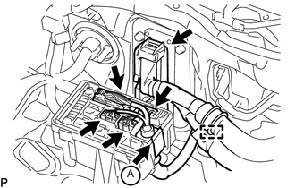
Disconnect the 2 connectors and detach the wire harness holder from the relay block.
-
Remove the bolt and disconnect the ground wire.
-
Disconnect the wire harness from the wire harness clamp holder.
-
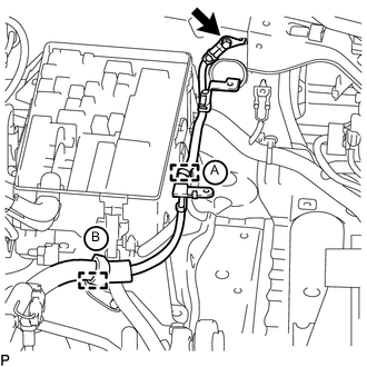
Remove the bolt and disconnect the ground wire from the body panel.
-
Using a clip remover, detach the ground wire clamp labeled A from the relay block side.
-
Disconnect the wire harness from the wire harness clamp holder labeled B.
-
Remove the nut and detach the generator positive (+) cable holder from the relay block.
-
Disconnect the generator positive (+) cable from the 2 clamps.
-
Disconnect the 2 connectors.
-
Using a clip remover, detach the 3 wire harness clamps.
-
for RHD:
Disconnect the 4 connectors and detach the wire harness tab labeled A from the relay block.
-
for RHD:
Disconnect the ECM connector.
-
for RHD:
Disconnect the wire harness from the wire harness clamp holder.
-
Disconnect the 8 connectors.
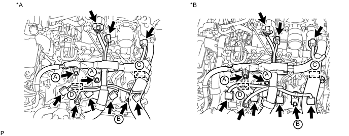
Text in Illustration *A w/ DPF *B w/o DPF -
Remove the bolt and the engine wire harness bracket labeled B.
-
Using a clip remover, detach the wire harness clamp labeled D.
-
Remove the 2 bolts and disconnect the engine wire protector labeled A.
-
for RHD:
Disconnect the wire harness from the wire harness clamp holder labeled C.
-
-
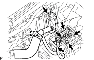
RH Side:
-
for LHD:
Disconnect the 4 connectors, and detach the wire harness holder from the relay block labeled A.
-
for LHD:
Disconnect the ECM connector.
-
for LHD:
Disconnect the wire harness from the wire harness clamp holder.
-
Disconnect the 7 connectors.
Text in Illustration *A w/ DPF *B w/o DPF -
Using a clip remover, detach the wire harness clamp.
-
Remove the 3 bolts and disconnect the engine wire protector labeled A.
-
Remove the bolt and the wire harness bracket labeled B.
-
Remove the screw grommet, nut and the glow plug wire harness labeled C.
-
Text in Illustration *A w/ DPF *B w/o DPF for RHD:
Disconnect the wire harness from the wire harness clamp holder.
-
for RHD:
Remove the bolt and wire harness clamp holder.
-
w/ Winch:
Remove the bolt and disconnect the ground wire.
-
-
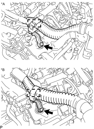
Rear Side:
-
Text in Illustration *A w/ DPF *B w/o DPF Using a clip remover, detach the wire harness clamp.
-
Remove the 2 bolts and 2 ground wires labeled C.
-
Remove the 2 bolts and disconnect the engine wire harness protector labeled B.
-
w/ DPF:
Disconnect the 3 connectors.
-
w/o DPF:
Disconnect the connector.
-
Remove the screw grommet, nut and disconnect the glow plug wire harness labeled A.
-
-
-
REMOVE NO. 2 FUEL PIPE SUB-ASSEMBLY (w/o DPF)
-
REMOVE NO. 6 INJECTION PIPE SUB-ASSEMBLY
-
REMOVE NO. 1 VACUUM SWITCHING VALVE ASSEMBLY (w/ DPF)
-
REMOVE NO. 1 VACUUM TRANSMITTING PIPE SUB-ASSEMBLY (w/ DPF)
-
REMOVE CYLINDER HEAD COVER SILENCER LH (w/ DPF)
-
REMOVE NO. 4 NOZZLE LEAKAGE PIPE (w/ DPF)
-
REMOVE INJECTION PIPE LH
-
REMOVE NO. 2 FUEL PIPE (w/ DPF)
-
REMOVE NO. 5 NOZZLE LEAKAGE PIPE (w/ DPF)
-
REMOVE COMMON RAIL ASSEMBLY LH
-
REMOVE FUEL FILTER TO INJECTION PUMP FUEL PIPE SUB-ASSEMBLY
-
DISCONNECT FUEL PUMP MOTOR WIRE
-
REMOVE NO. 5 INJECTION PIPE SUB-ASSEMBLY
-
REMOVE CYLINDER HEAD COVER SILENCER RH (w/ DPF)
-
REMOVE INJECTION PIPE RH
-
REMOVE COMMON RAIL ASSEMBLY RH
-
REMOVE NO. 1 INTAKE MANIFOLD INSULATOR (w/ Intercooler)
-
REMOVE NO. 2 INTAKE MANIFOLD INSULATOR (w/ Intercooler)
-
REMOVE CONNECTING WIRE (w/ DPF)
-
REMOVE NO. 3 NOZZLE LEAKAGE PIPE (w/ DPF)
-
REMOVE INTAKE PIPE
-
DISCONNECT NO. 2 ENGINE WIRE
-
REMOVE NO. 3 INTAKE MANIFOLD
-
REMOVE INTAKE MANIFOLD INSULATOR (w/ EGR System)
-
REMOVE EGR PIPE INSULATOR (w/ EGR System)
-
REMOVE EGR VALVE ASSEMBLY WITH EGR COOLER (w/ EGR System)
-
REMOVE EGR COOLER INSULATOR (w/ EGR System)
-
REMOVE NO. 3 NOZZLE LEAKAGE PIPE (w/o DPF)
-
REMOVE NO. 4 NOZZLE LEAKAGE PIPE (w/o DPF)
-
DISCONNECT NO. 6 WATER BY-PASS HOSE (w/o DPF)
-
REMOVE FUEL COOLER ASSEMBLY (w/o DPF)
-
REMOVE NO. 2 FUEL INJECTOR PROTECTOR (w/ DPF)
-
REMOVE NO. 1 FUEL INJECTOR PROTECTOR (w/ DPF)
-
REMOVE FUEL TUBE SUB-ASSEMBLY (w/ DPF)
-
REMOVE NO. 1 WATER BY-PASS PIPE
-
REMOVE NO. 2 NOZZLE LEAKAGE PIPE (w/ DPF)
-
REMOVE NO. 1 NOZZLE LEAKAGE PIPE (w/ DPF)
-
REMOVE FUEL HOSE BRACKET (w/ DPF)
-
REMOVE NO. 1 FUEL PIPE CLAMP (w/ DPF)
-
REMOVE NO. 1 INTAKE MANIFOLD
-
REMOVE NO. 2 INTAKE MANIFOLD
-
INSTALL NO. 1 AND NO. 2 ENGINE HANGER
-
Install the No. 1 and No. 2 engine hangers to the cylinder head RH and LH with the 4 bolts as shown in the illustration.
- Torque:
- 25 N*m { 250 kgf*cm, 18 ft.*lbf }
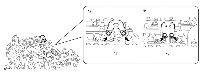
Tech Tips
No. 1 engine hanger 12281-51040 No. 2 engine hanger 12282-51040 Bolt 91671-80825 Text in Illustration *1 No. 1 Engine Hanger *2 No. 2 Engine Hanger *a RH *b LH
-
-
REMOVE AUTOMATIC TRANSMISSION ASSEMBLY
-
REMOVE MANUAL TRANSMISSION UNIT ASSEMBLY
-
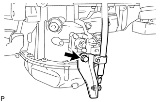
REMOVE CLUTCH RELEASE CYLINDER TO FLEXIBLE HOSE TUBE (for Manual Transmission)
-
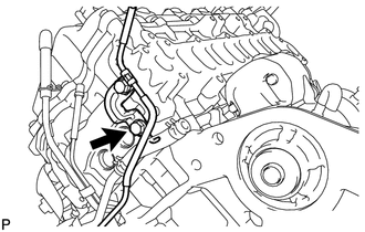
Remove the bolt and clutch release cylinder to flexible hose tube.
-
-
REMOVE ENGINE ASSEMBLY
-
Attach an engine sling device and hang the engine with a chain block.
-
Remove the 4 bolts from the engine mounting RH and LH side.
-
Lift the engine out of the vehicle carefully.
Note
-
Make sure the engine is clear of all wiring and hoses.
-
With the exception of installing the engine assembly to an engine stand or removing the engine assembly from an engine stand, do not perform any work on the engine while it is suspended, as doing so is dangerous.
-
Pay attention to the angle of the sling device as the engine assembly or engine hangers may be damaged or deformed if the angle is incorrect.
-
-
Place the engine onto a work bench.
-
-
REMOVE CLUTCH COVER ASSEMBLY (for Manual Transmission)
-
REMOVE CLUTCH DISC ASSEMBLY (for Manual Transmission)
-
REMOVE DRIVE PLATE AND RING GEAR SUB-ASSEMBLY (for Automatic Transmission)
-
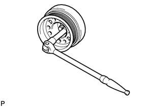
Using a wrench, hold the crankshaft.
Note
Do not turn the crankshaft counterclockwise.
If it is turned counterclockwise, check that the crankshaft pulley set bolt is not loose. If loose, tighten the bolt Click here.
- Torque:
- 108 N*m { 1101 kgf*cm, 80 ft.*lbf }
- or more
-
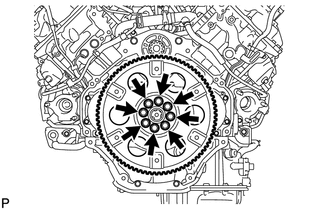
Remove the 8 bolts.
-
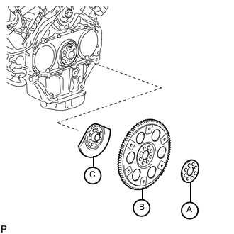
Remove the rear drive plate spacer labeled A, drive plate and ring gear labeled B and rear crankshaft balancer weight labeled C.
-
-
REMOVE FLYWHEEL SUB-ASSEMBLY (for Manual Transmission)
-
Using a wrench, hold the crankshaft.
Note
Do not turn the crankshaft counterclockwise.
If it is turned counterclockwise, check that the crankshaft pulley set bolt is not loose. If loose, tighten the bolt Click here.
- Torque:
- 108 N*m { 1101 kgf*cm, 80 ft.*lbf }
- or more
-
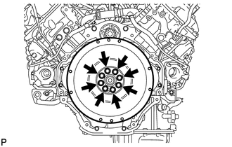
Remove the 8 bolts and flywheel.
-
-
INSTALL ENGINE STAND
-
Install the engine onto an engine stand with bolts.
-
Remove the 4 bolts and No. 1 and No. 2 engine hangers.
-
-
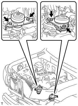
REMOVE FRONT ENGINE MOUNTING INSULATOR RH
-
REMOVE FRONT ENGINE MOUNTING INSULATOR LH